Page is loading ...

Pro 3.0 Series
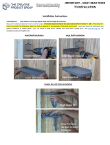
Warning: Excessive weight hazard!
Use two or more people to move, assemble or install cabinets and locker to avoid back injury.
Do not leave children unattended near cabinets. High risk of tipping if cabinets are installed
incorrectly: securely attach cabinets to the wall to avoid serious injury.
PRO3.INSTALL.REV.03

2
INDEX
Index - 2
Guidelines and weight capacity - 2-3
Parts list - 4
Tools needed - 5
Warranty - 5
Attaching feet - 6
Attaching casters - 7
Removing and inserting drawers - 8
Installing corner cabinet - 9
Stacking cabinets - 10
Installing worktop support bracket - 11
Attaching worktop( on 2 cabinets) - 12
Installing closet rod -13
Installing shelves - 14
Securing cabinets to drywall/stud wall -15
Hanging cabinets on stud wall - 16-19
Hanging cabinets on slatwall - 20-21
Fastening cabinets together - 22
Attaching light valance - 23
Utility hole - 24
500 lbs.
100 lbs.
100 lbs.
300 lbs.
200 lbs.
Lockers
Max 1000 lbs.
Tool Cabinets
Max 1000 lbs.
Wall Cabinets
Max 200 lbs.
100 lbs.
600 lbs.
300 lbs.
84” Worktop. Fits over 3 Cabinets
56” Worktop. Fits over 2 Cabinets
24” Corner Worktop
Worktop
Weight
Capacity
Base Cabinets
Max 1000 lbs.
100 lbs.
100 lbs.
100 lbs.
100 lbs.
100 lbs.
200 lbs.
Split Cabinets
Max 1000 lbs.
600 lbs.
100 lbs.
100
lbs.
200 lbs.
5 lbs.
300 lbs.
300 lbs.
300 lbs.
Unpacking
• Begin by placing the package on a covered at surface.
• Remove all cardboard, foam packaging material and clear plastic bags.
• Dispose / recycle all packaging materials.
• Verify all the contents in the box and gather the required tools. See “Parts Supplied” and “Tools Needed” on pages 4 and 5

3
500
lbs.
100 lbs.
100 lbs.
300
lbs.
200
lbs.
Lockers
Max 1000 lbs.
Tool Cabinets
Max 1000 lbs.
Wall Cabinets
Max 200 lbs.
100
lbs.
600 lbs.
300
lbs.
84” Worktop. Fits over 3 Cabinets
56” Worktop. Fits over 2 Cabinets
24” Corner Worktop
Worktop
Weight
Capacity
Base Cabinets
Max 1000 lbs.
100
lbs.
100
lbs.
100
lbs.
100
lbs.
100
lbs.
200
lbs.
Split Cabinets
Max 1000 lbs.
600 lbs.
100
lbs.
100
lbs.
200
lbs.
5
lbs.
300
lbs.
300
lbs.
300
lbs.

4
Mul-use Locker Sports Locker Two-Door Base Five-Drawer Tool Mulfuncon Wall Corner Wall
Hardware Box 1 1 1 1 1 1 1
#8 x 5/8" Wood Screw 2 2 4 4 4 0 4
1/4" x 0.9" Fender Washer 4 4 4 4 4 4 6
1/4" ID x 1/2" OD Washer 26 26 12 12 12 12 22
1/4" Lock Nut 10 10 4 4 4 4 4
1/4" x 2.5" Wall Screw 8 8 8 8 8 8 12
1/4"-20 x 5/8" Hex Bolts 10 10 4 4 4 4 8
Light Valence Bolts 0 0 0 0 0 2 2
Light Valence Nuts 0 0 0 0 0 2 2
Plasc Hole Caps 16 16 0 0 0 8 0
Power Cord Hole Rubber Grommet 1 1 1 0 0 0 0
She
lf Clips 24 24 0 0 0 6 0
Keys 2 2 2 2 2 2 2
Foot Aachment Screws 16 16 16 16 16 0 0
Adjustable Leveling Legs 4 4 4 4 4 0 0
Adjustable Steel Shelves 4 4 0 0 0
Closet Rod 1 1 0 0 0 0 0
Closet Rod Brackets with Rubber Coated Hooks 2 2 0 0 0 0 0
EVA Foam Drawer Liners 0 0 1 5 3 0 0
Garbage Bin 0 0 0 0 1 0 0
Parts Bins 0 0 0 0 24 0 0
Light Valence 0 0 0 0 0 1 1
Long Drawer Dividers 0 0 0 4 0 0 0
Short Drawer Dividers 0 0 0 8 0 0 0
Side Support Brackets 0 0 0 0 0 0 2
Easy Wall Hanging Brackets 2 2 2 2 2 2 3
1 0
NewAge Logo 1 1 0 0 0 0 0
Parts Supplied
Height-Adjustable
Steel Leveling Legs
Key
Washer
(1/4”x1/2”)
Wood Screw
(#8 x 5/8”)
Rubber
Grommet
Drawer Dividers
Wall Bracket Shelf Clips
Wall Screw
(1/4” x 2.5”)
Hex Bolt
(1/4” x 5/8”)
Full Width
Adjustable
Shelves
Clothes
Rod and
Hooks
Light Valence
Nut (M5)
Light Valence
Bolt (M5 x 12mm)
Support BracketLight Valance
Foot
Attachment
Screws
Lock Nut
(1/4”)
Fender Washer
(1/4”x0.9-in)
NewAge Logo

5
Tools Needed
1 x 12” Magnetic Leveler
1 x #2 Phillips Bit
1 x Tape Measure
1 x 7/16” socket
1 x Cordless Power Drill
1 x Stud Finder
1 x Pencil1 x Set
Square
1 x Hammer Drill 1 x Masonry Bit
1 x Adjustable wrench
1 x 7/16” Socket driver
wrench
1 x 8mm” Socket driver
wrench
1 x #2 Phillips
head screw driver
1 x #3 Phillips
head screw driver
[optional for masonry]
1
1 2 3
2
3
Manufacturer Warranty Limited Lifetime
1. Service calls to correct the installation of any NewAge products or to instruct you how to use or install them.
2. Damage resulting from improper handling or shipping of products, or products damaged by accident, misuse, abuse, re,
ood, improper installation, acts of God, neglect, corrosion, modication or mishandling.
3. Products damaged by improperly loading beyond the specied maximum weight capacity outlined in the instructions provided
with the product.
4. Repairs or replacement when your product is used in other than normal, single-family household use, such as a commercial
environment, or handled in anyway inconsistent with the installation instructions included with the product.
5. Cosmetic damage, including scratches, dings, dents or cracks in paint that do not aect the structural or functional capability
of the product.
6. Surfaces damaged due to chemical interaction resulting in corrosion of paint or metal.
7. Replacement parts for NewAge products outside Canada and the United States.
8. Replacement keys or locking mechanisms.
9. Loss of product contents due to theft, re, ood, accident or acts of God.
10. Shipping or freight fees to deliver replacement products or to return defective products.
11. Any labor costs during the limited warranty period.
When this product is installed, operated and maintained according to the instructions attached to or furnished with the product,
NewAge Products Inc. will replace the defective product or parts if the part fails as a result of defective materials or workmanship
for the Lifetime of the product.
NEWAGE PRODUCTS INC. WILL NOT PAY FOR:
IMPLIED WARRANTIES, INCLUDING TO THE EXTENT APPLICABLE WARRANTIES OF MERCHANTABILITY OR FITNESS FOR A PARTICULAR
PURPOSE, ARE EXCLUDED TO THE EXTENT LEGALLY PERMISSIBLE. ANY IMPLIED WARRANTIES THAT MAY BE IMPOSED BY LAW ARE LIMITED
TO ONE YEAR, OR THE SHORTEST PERIOD ALLOWED BY LAW. SOME STATES AND PROVINCES DO NOT ALLOW LIMITATIONS OR EXCLUSIONS
ON HOW LONG AN IMPLIED WARRANTY OF MERCHANTABILITY OR FITNESS LASTS, SO THE ABOVE LIMITATIONS OR EXCLUSIONS MAY NOT
APPLY TO YOU. THIS WARRANTY GIVES YOU SPECIFIC LEGAL RIGHTS, AND YOU MAY ALSO HAVE OTHER RIGHTS WHICH VARY FROM STATE
TO STATE OR PROVINCE TO PROVINCE
DISCLAIMER OF IMPLIED WARRANTIES; LIMITATION OF REMEDIES

6
Installing the Feet
1
Flip cabinet upside down,
locate holes at corners.
2
Stand & level feet.
Open cabinet, remove any shelves
or loose items.
Repeat step 3 for each corner.
5
4
Parts Needed.
16 X Foot
Attachment Screws
Align foot with edge of cabinet. Screw
in 4 x foot attachment screws using #3
Phillips Bit
3
Height-Adjustable
Steel Leveling Legs

7
Installing Casters
1
Flip cabinet upside down,
locate holes forming a square.
2
Open cabinet, remove any shelves
or loose items.
Repeat step 3 for each corner.
4
Parts Needed.
Align foot with holes. Attach with 4 hex
bolts, washers, and nuts.
3
16 X Lock Nut
(1/4”)
16 X
Washer
(1/4”)
16 X Hex Bolt
(1/4” x 5/8”)
4 x Casters
Note: Caster kits sold separately.
shopnewage.com

8
Right Side
Left Side
Slide In
Slide Out
Align Rails
Inserting Drawers.
Removing Drawers.
Installing the Drawers
Slide drawer out completely

9
Slide in corner and attach
remaining cabinets.
Installing Corner Worktop
1
Attach top to one cabinet using 1/4” x
5/8 hex bolts, nuts, and washers.
Attach second cabinet to top.
2
6”
or
4”
6”
or
4”
On adjacent edges attach 2 support
brackets to underside of corner top
using the supplied (4) 38 x 5/8” screws.
Parts Needed.
3
4x Washer
(1/4”)
4x # 8 x 5/8”
screw
4x 1/4” x 5/8
hex bolt
4x Lock Nut
(1/4”)
4
1
1 2 3
2
3
Note: Ensure there is enough assembly
room. Cabinets must be assembled away
from corner to access backs of cabinets.
X2
Important: For mounting top ush with back of
cabinet measure 6” in from corner, for mounting
top ush with front of cabinet measure 4” in from
corner and ush with edge.
2x Support
Bracket
1x Corner
Worktop

10
Stacking Cabinets
1
Locate punch holes on adjoining
surface and insert bolts.
Tighten all bolts
2
Attach cabinets using the supplied
1/4” x 5/8” hex bolts, washers, and
nuts.
Position a second base cabinet on
top of an existing base cabinet.
3
I
Parts Needed.
4 X Lock Nut
(1/4”)
8 X
Washer
(1/4”)
4 X Hex Bolt
(1/4” x 5/8”)
4

11
Installing Worktop
Side Support Bracket
Note: Support bracket included with locker.
X2
Fasten nuts, bolts, and lock washers.
2
Tighten nuts & bolts.
Parts Needed.
4
3
5
Align bracket.
Level bracket and ensure it is at the
same height as the base cabinet.
1
Open locker and locate holes on either side.
2 X Lock Nut
(1/4”)
4 X
Washer
(1/4”)
2 X Hex Bolt
(1/4” x 5/8”)
1x Support
Bracket

12
Mounting the Worktop (On 2 Cabinets)
1
Optional: For locker support bracket.
X4 X2
X2
X2
Locate 2 punch holes both sides.
2
Drill into the worktop using the #8 x 5/8” wood screwes.
X2
Use 2 washers & #8 x 5/8” wood screws.
Provided in the locker packaging.
Place worktop on cabinets.
3
I

13
Inserting Locker Utility Rod and Hangars
1
Ensure rear ange slides down behind
clips and that the bracket is secure.
Place hangar against locker wall
above supports.
2
Open cabinet Doors. Insert clips into slots in corners.
Rotate to engage.
4
3
5
6
Interior
Side View
Interior
Side View
Lower rod into cradle.

14
Inserting Cabinet Shelves
1
Lower shelf onto supports.Insert shelf on a angle and rotate
to level position.
Insert shelf clip on slight angle
and rotate to level position.
2
Stand cabinet up.
4
3
5
6
Rest shelf on supports.
Insert remaining shelves.
Interior
Side View
Interior
Side View

15
Mounting Cabinets (Drywall/Studded Wall)
1
Level cabinet
Gather parts.
2
Align cabinet
to stud marks.
• Follow steps 3 to 5.
• Drill 4 pilot holes through the
perforated strip with hammer drill &
masonry bit.
• Use 4 x (
2 ¼” x ¼” )Tapcon Concrete
Anchor into wall. (Not Included)
• OR 4 x (#10 x 2” )Screw with 3/16”
masonry plug into wall. (Not Included)
• Follow Step 6.
Use stud nder to locate the studs
and mark the wall with a pencil.
4
3
Wall Screw
(1/4” x 2.5”)
Wall Washer
(1/4”)
5
Place cabinet tight
against the wall.
X4
6
Masonry.
Drill 4 wall screws and washers
through perforated holes into studs.
Wall & Locker: 4 wall screws and 4 washers
Corner Wall: 6 wall screws and 6 washers
Base & Tool Cabinet: 2 wall Screws and 2 washers

16
Hanging Cabinets on Wall (optional)
Planning the general position of cabinets.
Step A. Determine the height o the ground you would like the base and locker
cabinets to be and make a horizontal mark at this position.
Step B. Next mark the width of each cabinet in the intended position and ensure
the wall studs fall at least 1.25” in from the edge of the cabinets. This will
ensure there is no interference with the edges of the cabinet and the
wall bracket when hanging the cabinet on the wall.
Note: Ensure there are two studs for the locker to be mounted on as it is easiest to
start the installation with the locker rst. Due to the spacing of the wall studs it is
possible that some base or wall cabinets will only have one stud they will attach
to; This is acceptable as long as the cabinet is bolted to another securely mounted
cabinet.
Parts Needed.
Lag Screw
(1/4” x 2.5”)
Height from Floor
Floor
Wall
studs
must fall
1.25” or
more
from
sides of
cabinet
Wall
studs
must fall
1.25” or
more
from
sides of
cabinet
A
A
B
B
Width of Cabinets
Wall Stud
Cabinet Width
Cabinet Layout
2
1
Use stud nder to locate the studs
and mark the wall with a pencil.

17
Planning the general position of cabinets. (cont.)
Step C. Measuring up from the line marked in Step A, make a horizontal mark
at the following heights where they intersect the wall stud marks to
determine where the top of the cabinet will be (and where the
hanging bracket will be installed).
1. Locker: Measure 80” vertically from base line and mark at stud locations.
2. Base: Measure 32.25” vertically from base line and mark at stud locations.
3. Wall cabinets: Measure 80” vertically from base line and mark at stud
locations (if installing ush with top of locker).
Step D. Ensure the cabinets will be at a suitable working height and that your
wall cabinets are not out of reach.
Note: The working surface of the base cabinets will be 1.25” higher than
the cabinet with the top installed.
3
Height from Floor
Floor
Locker & Wall 80”
Base Cabinets 32.25”
A
C
C
Hanging Cabinets on Wall (cont.)

18
Hanging Cabinets on Wall (cont.)
4
Hanging cabinets on wall.
Align the top of the wall hanging brackets with the lines marked for
the position of the top of the cabinets(Step C) and attach
the brackets securely into the studs using the supplied
lag bolts and washers.
Note: It is possible to oset the bracket to one side or the other if the bracket
is positioned close to the edge of the intended cabinet position by using the
secondary hole positions on the bracket.
Height from Floor
Floor
Locker & Wall 80”
Base Cabinets 32.25”
A
C
C
WALL
CABINET FRONT
WALL
5
Lift cabinet into place over the brackets and
ush with the wall, and lower into place.

19
Hanging Cabinets on Wall (cont.)
Bolt each subsequent cabinet to the
previous one using the supplied ¼” x 5/8”
hex bolts and lock nuts provided in each
base and wall cabinet.
6
Parts Needed.
Lock Nut
(1/4”)
Washer
(1/4”)
Hex Bolt
(1/4” x 5/8”)
6
X4
X4
WARNING: Wall backets are not designed to support the weight of a loaded cabinet.
Cabinets must be secured to the wall using supplied 1/4” x 2.5” lag screws.

20
WALL STUD
LOCKER
X4
Securing to Wall
Using (4) 1/4” x 2.5” lag screws and washers secure
each cabinet to wall stud from inside cabinet.
Parts Needed.
Bolt
(1/4” x 2.5”)
Wall Washer
(1/4”)
7
Note: Brackets are not designed to support the weight of a loaded cabinet. Cabinets
must be secured to the wall using supplied 1/4” x 2.5” lag screws.
Note: Slatwall Brackets for use with standard 3” slatwall Sold Separately. Check with your
slatwall supplier to determine the rated capacity of your slatwall. DO NOT OVERLOAD.
Hanging Cabinets on Slatwall
1
Insert bolts through slatwall bracket.
Parts Needed.
Wall Bolt
(1/4” x 5/8”)
Wall Washer
(1/4”)
Slatwall Bracket
Lock Nut
(1/4”)
Note:
Do not load cabinet without rst
securing to the wall.
/