Page is loading ...

IMPORTANT:
Go to www.extron.com for the complete
user guide, installation instructions, and
specifications before connecting the
product to the power source.
DTP T DSW 4K Series • Setup Guide
This setup guide provides instructions for an experienced installer to set up and operate the Extron DTP T DSW 4K series of
twisted pair (TP) switchers.
Front Panel
POWER
12V
2
1.4 A MAX
Rx GTx RxTxG
RS-232 IR
RxTx
1
RGB, YUV HDMI DP
SIG LINK
OUT
AUDIO
CONTACT IN RS-232TALLY OUT
3
123G 123+V
INPUTS
OVER TP REMOTE
DTP
HDBT
AUTO
SWITCH
DTP T DSW 4K 333
3
CONFIG
231
STATUS
SIGNAL
HDCP
AUTO
2
NORMAL
1
MODE
B
C
C CA
G
BC C CA
D E
F
E
D
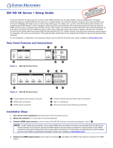
Figure 1. DTP T DSW 4K Front Panel
A
Auto Switch LED — Lights green when auto switching is enabled.
B
USB Config port — Updates rmware and congures the device through SIS commands or software control.
C
Input selection buttons — Select the active input and used to change switching modes. Each button has an associated
LED which lights green to indicate input selection status.
D
Input Signal LEDs — Light green when a signal is detected on the associated input.
E
Input HDCP LEDs — Light green when HDCP presence is detected on the associated input.
Rear Panel
POWER
12V
2
1.4 A MAX
Rx GTx RxTxG
RS-232 IR
RxTx
1
RGB, YUV HDMI DP
SIG LINK
OUT
AUDIO
CONTACT IN RS-232TALLY OUT
3
123G 123+V
INPUTS
OVER TP REMOTE
DTP
HDBT
AUTO
SWITCH
DTP T DSW 4K 333
3
CONFIG
231
STATUS
SIGNAL
HDCP
AUTO
2
NORMAL
1
MODE
B
C
C CA
G
BC C CA
D E
F
E
D
Figure 2. DTP T DSW 4K Rear Panel
A
DC Power connector
B
Analog audio input connector
C
RGB, HDMI, DisplayPort input connectors
D
DTP/HDBaseT output
E
DTP/HDBaseT mode switch
F
Over TP RS-232/IR connectors
G
Remote Contact, Tally, and RS-232 connectors
100-240V ~ -- A MAX
1
2
CONFIGURABLE
HDMI
HDMI
5
6
7
8
C
RS-232 IR
RS-232 IR
Tx Rx Tx RxG
Tx Rx Tx RxG
Tx Rx Tx RxG
HDMI
A
B
3
4
INPUTS
OUTPUTS
Tx Rx
RS-232
G
LAN
2x25W(8
RESET
AUDIO INPUTS
OUTPUTS
REMOTE
LL1R R
L2
R
L
3
CLASS 2 WIRING
L4
R
L5R
+48V
+48V
12
LR
VARIABLE
IN1608 SA
2
MIC/LINE
L6
R
SIG LINK
DTP IN
SIG LINK
DTP IN
SIG LINK
DTP OUT
50/60 Hz
RS-232 IR
OVER DTP
OVER DTP
OVER DTP
AMPLIFIED OUTPUT
SCALING PRESENTATION SWITCHER
INPUTS
1
HDCP
SIGNAL
OUTPUTS
ENTER
MENU
Extron
2 3 4 5 6 7 8 A B C
INPUTS
1 2 3 4 5 6 7 8
CONFIG
POWER
12V
2
--A MAX
Rx GTx RxTxG
RS-232 IR
RxTx
1
RGB, YUVHDMIDP
SIG LINK
OUT
AUDIO
CONTACT IN RS-232TALLY OUT
3
123G 123+V
INPUTS
OVER TP REMOTE
DTP
HDBT
T
x
R
x
RS
-23
2
G
LAN
2x25W
(
8
R
E
S
E
T
REM
O
T
E
L
C
LA
SS
2 WIRIN
G
A
MPLIFIED OUTPUT
SC
ALIN
G
PRE
S
ENTATI
O
N
S
WIT
C
HE
R
LR
POWER
12V
0.7A MAX
AUDIO
SIG LINK
DTP IN
OUTPUTS
12345678
100
LINK
ACT
COM
IR/S
TX
RX
TX
RX
RTS
CTS
R
5
1
6
2
7
3
8
4
RELAY
FLEX
I/O
5
1
6
2
3
1
4
2
eBUS
ACT LIMIT
OVER
SWITCHED
12VDC
3
1
4
OVER
2
LIMIT
IR
7
3
8
4
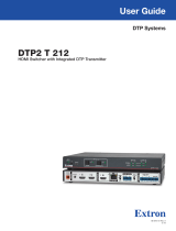
IPCP 505
TLP 1000TV
IPCP 505
IN1608
DTP HDMI 330 Rx
Projector
Extron
DTP T DSW 4K 333
Switcher
Ethernet
HDMI
PC
Blu-Ray
RGB
Laptop
XTP DTP 24 Cable
330'
HDMI
DisplayPort

2
DTP T DSW 4K Series • Setup Guide (Continued)
NOTE: The following descriptions refer to figure 2 on the previous page.
A
DC Power connector — Wire and plug the included external 12 VDC 1.5 A power supply into this 2-pole connector. The
DTP T DSW 4K series can provide remote power to a compatible receiver (see the DTP T DSW 4K Series User Guide for
wiring and remote power information).
B
Analog audio input connector — Wire and connect an audio source to this 3.5 mm
tip-ring-sleeve (TRS) connector for analog audio input. Wire the connector as shown to the right.
C
Input connectors
• RGB — Connect a video source to this 15-pin HD connector.
• HDMI — Connect a video source to this HDMI connector.
• DisplayPort — Connect a video source to this DisplayPort connector.
D
DTP/HDBaseT output — Use a shielded twisted pair (STP) cable to connect the output to the input of a compatible
receiver.
ATTENTION:
•
Do not connect these outputs to a telecommunications or computer data network.
• Ne connectez pas ces appareils à des données informatiques ou à un réseau de télécommunications.
• DO NOT connect an HDBaseT unit if using DTP transmission. The power carried over DTP may damage the
unit.
• Ne PAS connecter une unité HDBaseT si vous utilisez la transmission DTP. L’alimentation transmise sur DTP
peut endommager l’unité.
E
DTP/HDBaseT configuration switch — Set this 2-position, recessed switch to congure the output between HDBaseT
and DTP modes. When congured for HDBaseT, connect an HDBaseT-compatible receiver to the DTP/HDBaseT output.
When congured for DTP, connect a DTP-compatible receiver to the DTP/HDBaseT output.
NOTES:
• When the switch is set to DTP mode and the unit is locally powered, the DTP T DSW 4K unit can provide
remote power to a compatible receiver. The unit cannot receive remote power in either mode.
• When the switch is set to HDBaseT mode, remote power is disabled and power supplies are required for both
transmitter and receiver. Analog audio is enabled, but incompatible with third-party HDBaseT devices.
F
Over DTP RS-232/IR connectors — Use a 3.5 mm, 5-pole captive
screw connector to pass bidirectional RS-232 and IR control
between compatible devices. Wire the connector as shown in the
gure to the right.
G
Remote contact in, tally out, and RS-232 connectors
• Contact In — Connect contact closure devices or Extron
“Show Me” cables to this 4-pole captive screw connector (see gure to right for wiring
instructions).
• Tally Out — Connect tally devices or Extron “Show Me” cables to this 4-pole captive screw
connector (see gure to right for wiring instructions).
• RS-232 — Connect a 3.5 mm, 3-pole captive screw connector for RS-232 control of the unit (see
gure below for wiring instructions).
Ground (shared)
Transmit pin on connected unit
Receive pin on connected unit
Connected RS-232 and
IR Device Pins
Transmit pin for IR control
Receive pin for IR control
RxTx
RS-232 IR
RxTx
G
OVER TP
Sleeve ( )
Ring (R)
Tip (L)
3.5 mm Stereo Plug Connector
(unbalanced)
CONTACT IN
+V321
G321
TALLY OUT
REMOTE
Red
Black
“Show Me” Cable
Tx Rx G
RS-232
Ground
Transmit pin on connected uni
t
Receive pin on connected unit

3
Installation
1. Mount the DTP T DSW 4K unit in a suitable location (see the Mounting section of the DTP T DSW 4K Series User Guide for
mounting options). Follow the instructions provided with the mounting kit.
2. Connect the USB or RS-232 connector (see
G
on the previous page) to a PC for conguration and maintenance. Use SIS
commands or the Extron PCS program to congure EDID Minder, mute the video signal, mute the audio signal, adjust the
video color bit depth, or monitor the signal and HDCP status, as required (see the DTP T DSW 4K Series User Guide for more
information).
3. Connect the rear panel transmitter output (see
D
on the previous page) to a rear panel receiver input using shielded twisted
pair (STP) cable.
NOTES:
• The DTP T DSW 4K 233 can transmit video, control, and audio (if applicable) signals up to 230 feet (70 meters).
• The DTP T DSW 4K 333 can transmit video, control, and audio (if applicable) signals up to 330 feet (100 meters).
For optimal performance, Extron highly recommends the following:
• RJ-45 termination with STP cable must comply with TIA/EIA-T568B wiring standard for all connections. For more
information on cable wiring and termination, see the full product user guide at www.extron.com.
• Use shielded twisted pair cable, 24 AWG solid conductor or better, with a minimum cable bandwidth of 400 MHz.
ATTENTION:
• Do not use Extron UTP23SF-4 Enhanced Skew-Free AV UTP cable or STP201 cable.
• N’utilisez pas le câble AV Skew-FreeUTP version améliorée UTP23SF d’Extron ou le câble STP201.
• Use shielded RJ-45 plugs to terminate the cable.
• Overall transmission distance capabilities vary depending on the number of patches used. If possible, limit the number of
patches to 2 total.
• If RJ-45 patches must be used in the system, Extron recommends shielded CAT 6 (or better) patches.
4. Connect control devices.
a. Connect contact closure devices or Extron “Show Me” cables to the Contact In 4-pole captive screw connector (see
G
on the previous page).
b. Connect tally devices or Extron “Show Me” cables to the Tally Out 4-pole captive screw connector (see
G
on the
previous page).
c. For serial RS-232 control, connect a host device to the RS-232 3-pole captive screw connector (see
F
on the previous
page) or the 3-pole captive screw connector (see
G
on the previous page).
d. For control or conguration through USB, connect a host device to the front panel USB mini-B port (see
B
on page 1).
5. Connect and power on related devices to the switcher and compatible receivers.
6. At the power outlet, connect the power supply to power on the unit (see the DTP T DSW 4K Series User Guide for information
on power connector wiring and remote power).

68-2761-50 Rev. B
12 18
© 2015-2018 Extron Electronics — All rights reserved. All trademarks mentioned are the property of their respective owners. www.extron.com
/