1
AC 102 and AC+USB 311 No AC Power Modules
for the Cable Cubby Enclosures • Installation Guide
The AC102 and AC+USB 311 No AC Power Modules provide slots for installing one or two compatible AC outlets (purchased
separately) for powering and charging laptops and other portable devices. The No AC Power Modules are compatible with the
following outlets:
• Legrand Israel 572124 — White • Legrand India 573471 — White
• Legrand Israel 572624 — Magnesium • Legrand India 573671 — Magnesium
See the CAUTION and ATTENTION notifications before installing the outlets and mounting the power module. Follow the steps
below to properly install and secure the module.
Installing the AC Outlets in the Power Modules
CAUTION:
ATTENTION :
• All electrical installation should be performed by qualified personnel in accordance with local and national building, fire
and safety, and electrical codes.
• Toute installation électrique devrait être effectuée par un personnel qualifié, conformément aux codes du bâtiment, aux
codes incendie et sécurité, et aux codes électriques locaux et nationaux.
• To ensure proper electrical grounding, use the provided #6-32 grounding screws and star washers.
• Afin d’assurer une mise à la terre correcte, utilisez les fixations de mise à la terre #6-32 et les rondelles en étoile fournies.
ATTENTION: Follow all national and local building and electrical codes that apply to the installation site. Extron is not liable nor
responsible for damage or injury as a result of installing this product. It is the responsibility of the qualified installer to ensure
applicable safety, compliance, and technical steps have been performed in accordance to regulatory, building and electrical
standards.
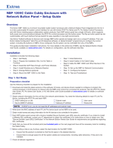
The AC 102 No AC power module has two slots at the top, through which you can
access two sets of cables in order to wire them to the outlets. The AC+USB 311 has one slot
and one set of cables for wiring. Each set consists of the following three colored cables:
• Brown — Live • Blue — Neutral • Green — Ground
To wire the outlets to the module:
1. Each set of cables (one brown, one blue, and one green) is zip-tied together and placed
inside the module (see
1
in the illustration at right). Pull one zip-tied set of cables out
through each slot, so that the loose ends of the cables are accessible (
2
).
2. Remove the partially-severed insulation from the ends of the cables to expose the bare
wires (
3
).
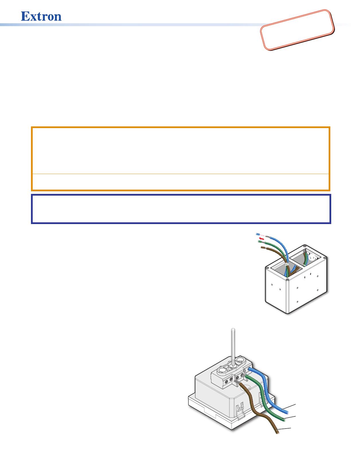
3. Place the module on a flat surface with the slots facing up and the word Top (between two
arrows pointing up) facing toward you, as shown at right.
4. Attach the wires to each outlet as follows:
a. Loosen the three screws on the back of the outlet (see
1
in the illustration below, right).
b. Insert each wire into the appropriate captive screw
connector (use either of the two holes):
• Live (brown) cable — L connector (
2
)
• Ground (green) cable — Ground connector (
3
),
labeled with __.
• Neutral (blue) cable — N connector (
4
)
c. After inserting each wire, tighten the screw above it to
hold it in place (
1
). Pull gently on each wire to ensure
it is securely attached.
240V~ 50-60Hz 10A MAX TOTAL
TOP
11
3
3
2
2
L
N
Blue = Neutral
Green = Gr
Brown = Live
1
1
3
3
2
2
4
4
Figure 2. Connecting Wires to AC Outlet
IMPORTANT:
Go to www.extron.com for the
complete user guide and installation
instructions before connecting the
product to the power source.
Figure 1. AC 102 Module with Wires