1. DESCRIPTION
The BA304G-SS-PM and the BA324G-SS-PM are panel
mounting intrinsically safe digital indicators that display the
current owing in a 4/20mA loop in engineering units. They
are loop powered, but only introduce a 1.2V drop into the loop.
Both models are electrically similar, but have dierent size
displays.
BA304G-SS-PM 4 digits 34mm high
316 stainless steel enclosure
BA324G-SS-PM 5 digits 29mm high + 31 segment bargraph
316 stainless steel enclosure
This abbreviated instruction sheet is intended to assist with
installation and commissioning, a comprehensive manual
describing safety certication, system design and calibration
is available from the BEKA sales oce or may be downloaded
from our website.
Both models have IECEx, ATEX and UKEX gas and dust
intrinsic safety certication. The certication label which
is located on the top of the instrument enclosure shows
the certicate numbers and certication codes. Copies of
certicates can be downloaded from www.beka.co.uk.
Typical certication information label
1.1 Installation in certied enclosure
In addition to conventional intrinsic safety certication, these
indicators may be installed in a certied Ex e, Ex p or Ex t
panel enclosure without invalidating the panel enclosure’s
certication. Please see the full instruction manual for details.
a. When installed in an Ex e panel enclosure, the indicator should
be powered by an appropriately rated Zener barrier or galvanic
isolator located in a safe area.
b. When pressurised, an Ex pyb enclosure reduces the equipment
protection level (EPL) inside the enclosure from Gb (Zone 1) to
Gc (Zone 2). When correctly installed in an Ex pyb enclosure
the indicator should be powered by an appropriately rated
Zener barrier or galvanic isolator located in a safe area
c. When pressurised, an Ex pxb enclosure reduces the
equipment protection level (EPL) inside the enclosure from Gb
(Zone 1) to non-hazardous. When correctly installed in an
Ex pxb enclosure the indicator may therefore be used without a
Zener barrier or galvanic isolator.
d. When pressurised, an Ex pzc enclosure reduces the equipment
protection level (EPL) inside the enclosure from Gc (Zone
2) to non-hazardous. When correctly installed in an Ex pzc
enclosure the indicator may therefore be used without a Zener
barrier or galvanic isolator.
e. When correctly installed in a certied Ex t enclosure the indicator
may be used without a Zener barrier or galvanic isolator.
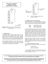
2. INSTALLATION
Both models have a 316 stainless seel cast front panel with
a toughened glass window which are impact resistant and
provide IP66 protection. The rear of the instrument has IP20
protection.
82
12
66
106
84
90
11
12
M5 CLEARANCE
4 OFF
Indicator
outline
12
Fig 1 Recommended panel cut-out dimensions
Instrument
panel
Secure indicator
onto panel using
4 off M5x16 screws
and spring washers
Position black moulded
silicone gasket onto the
indicator casing
E
P
Fig 2 Installation procedure
122
120
Scale Card
tab
+
+
-
14
13
12
Separately powered
Loop powered
Common
10
11
9
8
1
2
3
4
+
Terminals
for optional
alarms
Terminals
for optional
backlight
4/20mA
input
Terminals 2 & 4
internally linked
for joining return
4/20mA wire.
-
-
+
Ex e, Ex p or Ex t panel enclosure certification
maintained when BA304G-SS-PM is fitted
40
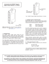
Fig 3 Terminals and overall dimensions
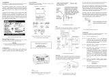
EMC
For specied immunity all wiring should be in screened
twisted pairs, with the screens earthed in the safe area.
2-wire
Tx
Safe areaHazardous area
4/20mA
Load
3 4 2 1
Instrument
power
supply
+
0
28V 93mA; 300Ω
barrier
Diode
return barrier
2-channel
Fig 4 Typical measurement loop
Scale card
The indicator’s units of measurement and tag information
are shown above the display on a slide-in scale card.
New instruments are tted with a scale card showing the
information requested when the instrument was ordered, if
this is not provided a blank scale card will be tted which can
easily be marked on-site. Custom printed scale cards are
available from BEKA associates.
To remove the scale card, carefully pull the tab perpendicularly
away from the rear of the indicator assembly. See Fig 3 for
the location of the scale card tab.
To replace the scale card carefully insert it into the slot on the
right hand side of the input terminals which is shown in Fig 3.
Force should be applied evenly to both sides of the scale card
to prevent it twisting. The card should be inserted until about
2mm of the transparent tab remains protruding.
EP
Fig 5 Inserting scale card into the instrument assembly.
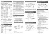
3. OPERATION
All models are controlled and calibrated via four front panel
push buttons. In the display mode i.e. when the indicator is
displaying a process variable, these push buttons have the
following functions:
( While this button is pushed the indicator will display
the input current in mA, or as a percentage of the
instrument span depending upon how the indicator
has been congured. When the button is released
the normal display in engineering units will return.
The function of this push button is modied when
optional alarms are tted to the indicator.
& While this button is pushed the indicator will display
the numerical value and analogue bargraph* the
indicator has been calibrated to display with a
4mAΦ input. When released the normal display in
engineering units will return.
* While this button is pushed the indicator will display
the numerical value and analogue bargraph* the
indicator has been calibrated to display with a
20mAΦ input. When released the normal display
in engineering units will return.
) No function in the display mode unless the tare
function is being used.
( + & Indicator displays rmware number followed by
version.
( + * Provides direct access to the alarm setpoints when
the indicator is tted with optional alarms and the
AC5P access setpoints function has been enabled.
( + ) Provides access to the conguration menu via
optional security code.
Note * BA324G-SS-PM only
Φ If the indicator has been calibrated using
the CAL function, calibration points may not be 4
and 20mA.
Abbreviated Instruction for
BA304G-SS-PM & BA324G-SS-PM
intrinsically safe panel mounting
loop powered indicators
Issue 2
24th November 2022
BEKA associates Ltd. Old Charlton Rd, Hitchin, Hertfordshire,
web: www.beka.co.uk
EP
TAG NUMBER SCALE
9.304
EP
TAG NUMBER SCALE
99.324