Page is loading ...

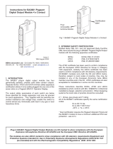
1. DESCRIPTION
The BA427E is an intrinsically safe loop powered Set Point
Station that enables the current owing in a 4/20mA loop to be
adjusted from within a hazardous area using the instruments
front panel push buttons. The BA427E incorporates a 5 digit
display that may be calibrated to show the 4/20mA output current
in any linear engineering units. A 31 segment bargraph indicates
the current output. The Set Point Station output current may
also be controlled by an external three wire quadrature encoder.
An optional factory tted backlight, which may be loop or
separately powered is available.
This abbreviated instruction sheet is intended to assist with
installation and commissioning, a comprehensive instruction
manual describing safety certication, system design and
calibration may be downloaded from the BEKA website www.
beka.co.uk/manuals.html or may be requested from the BEKA
sales oce.
The BA427E has IECEx, ATEX & UKEX intrinsic safety
certication for use in ammable gas and dust atmospheres.
The certication label, which is located on the top of the
instrument enclosure shows the certicate numbers and the
certication codes. Copies of certicates may be downloaded
from www.beka.co.uk
Certication information label
2. INSTALLATION
The BA427E has IP66 front of panel protection, but it is
good practice to install the instrument where the front is
protected from severe weather conditions and the display is
not subjected to continuous direct sunlight. The rear of the
instrument has IP20 protection.
Special Conditions for Safe use
Potential electrostatic charging hazard clean only
with a damp cloth
Care should be taken when cleaning the front of the
instrument, although the caution only applies to the
enclosure as the glass window and keypad will not
support an electrostatic charge.
IIIC dust atmospheres
When installed in a IIIC conductive dust atmosphere,
the instrument terminals should have at least IP6X
protection. This requirement does not apply for
installations in a gas atmosphere or in IIIA or IIIB dusts.
Insert panel clamp into recess & gently pull it onto
the dovetail. Engage screw and turn clockwise to
tighten clamp. Recommended tightening torque
22cNm (1.95lbf.in) Equivalent to finger tight plus
one half turn. DO NOT OVERTIGHTEN
Insert instrument
into the panel
from the front
Position gasket
behind instrument
bezel
Align foot and body by
turning screw anticlockwise
Fig 2 Installation procedure
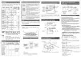
EMC
For specied immunity all wiring should be in screened twisted
pairs, with the screens earthed at one point within the safe area.
28V, 93mA Zener barrier
Diode return barrier
Safe areaHazardous area
4/20mA 4/20mA
BA427E
6.1V min
3 1
Instrument
power
supply
+24V
0V
2-channel
Speed
controller
Fig 3 Typical remote set point application
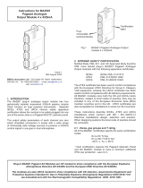
Scale card
The Set Point Station’s units of measurement are shown on a
printed scale card visible through a window at the right hand side
of the display. The scale card is mounted on a exible strip that is
inserted into a slot at the rear of the instrument as shown below.
Fig 4 Inserting scale card into slot at the rear of BA427E
Thus the scale card can easily be changed without removing the Set
Point Station from the panel or opening the instrument enclosure.
New Set Point Stations are supplied with a printed scale
card showing the requested units of measurement, if this
information is not supplied when the instrument is ordered a
blank card will be tted.
A pack of self-adhesive scale cards printed with common
units of measurement is available as an accessory from BEKA
associates. Custom printed scale cards can also be supplied.
To change a scale card, unclip the end of the exible strip that
is accessible from the rear of the instrument by gently pushing
it upwards and pulling it out of the enclosure as shown in Fig 4.
Peel the existing scale card from the exible strip and replace
it with a new printed card, which should be aligned as shown
below. Do not t a new scale card on
top of an existing card.
Align the self-adhesive printed scale
card onto the exible strip and insert
the strip into the instrument as shown.
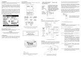
3. OPERATION
The BA427E Set Point Station is
controlled and congured via four front
panel push buttons located below the
display. In the operating mode i.e. when
the Set Point Station is controlling the
loop current and the display is showing
the output in engineering units, these
push buttons have the following functions:
E* + ▼ Output current slowly decreases. After ve seconds
the rate of change accelerates so that large changes
may be made quickly. Push E button rst followed by
▼ button to decrease output current.
E* + ▲ Output current slowly increases. After ve seconds
the rate of change accelerates so that large changes
may be made quickly. . Push E button rst followed by
▲ button to increase output current.
* Optional
E Pushing this button for 5 seconds enables the Set
Point Station output to be entered digit by digit in
engineering units using the ▲ or ▼ push button to
adjust the ashing digit and the P button to move
control to the next digit. When set as required
pressing the E button will enter the new set point
value and the output current will change.
P While this button is pushed the BA427E Set Point
Station will display one of three alternatives depending
upon how the instrument has been congured:
Output current in mA
Output as a % of span
Access to pre-set outputs
The display will ash. While continuing to press the
P button, operating the ▼ or ▲ button will show the
identication of the pre-set closest to the present Set
Point Station output, followed by the pre-set value.
Operating the ▼ or ▲ button will scroll through the
ve pre-sets and an ‘Abort’ position.
Releasing both buttons will leave the selected pre-set
value or ‘Abort’ legend ashing for ten seconds, during
which time operating the E button will update the Set
Point Station output to the displayed pre-set value. If
the E button is not operated during this period, the
Set Point Station output will not be changed and the
original engineering display will be shown.
▼
While this button is pushed the Set Point Station will
display the numerical value the Set Point Station has been
calibrated to display with a 4mA output. When released
the normal display in engineering units will return.
▲
While this button is pushed the Set Point Station will
display the numerical value the Set Point Station has been
calibrated to display with a 20mA input. When released
the normal display in engineering units will return.
P + ▼ Firmware number followed by version.
P + E
Access to conguration menu via optional security code.
Abbreviated Instructions for
BA427E intrinsically safe panel
mounting Set Point Station
Issue 5
12th October 2022
BEKA associates Ltd. Old Charlton Rd, Hitchin, Hertfordshire,
SG5 2DA, UK Tel: +44(0)1462 438301 e-mail: [email protected]
web: www.beka.co.uk
BA427E
Set Point Station
+
1 2 3 4
Terminals 2 & 4 are
internally linked for
joining return
4/20mA wire
Terminals for
optional external
rotary encoder
12 13
+
Terminals for
optional backlight
14
--
5 6 7
A B C
Common
Separately
powered
Loop powered
Common
96
65
Cut-out dimensions
Recommended for all installations.
Mandatory to achieve an IP66 seal between the
BA427E Set Point Station and the instrument panel
90 +0.5/-0.0 x 43.5 +0.5/-0.0mm
7.5
48
Panel cut-out
I
n
s
e
r
t
Unlock
Lock
Align on
these
edges
Scale
card
Support panel wiring to prevent vibration damage
Fig 1 Cut out dimensions and terminals
Fig 5 Fitting
scalecard to
exible strip

4. CONFIGURATION
The BA427E Set Point Station is supplied calibrated as requested when ordered, if not specified default configuration will be supplied but can easily be changed on-site.
Fig 6 shows the location of each function within the configuration menu with a brief summary of the function. Please refer to the full instruction manual for detailed configuration information.
Access to the configuration menu is obtained by pressing the ( and ) buttons simultaneously. If the Set Point Station security code is set to the default 0000 the first parameter rE5n will
be displayed. If the Set Point Station configuration menu is protected by a non-default security code, CodE will be displayed and the non-default code must be entered to obtain access to
the menu.
Fig 6 Configuration menu
Old Charlton Rd, Hitchin, Hertfordshire, SG5 2DA, UK
Tel: +44(0)1462 438301 Fax: +44(0)1462 453971
e-mail: [email protected] web: www.beka.co.uk
Full instructions, certificates,
declarations of conformity and
datasheets can be downloaded from
http://www.beka.co.uk/ba427e
P
EE
P
E E
P E
Security Code
Enter code by
pressing
or
and to
move to next digit
Code 0000 allows
direct access
to the menu
P
P E
E
P E
P E P E
P P
P E
E
EP E
P E P E
E
EP E
P E
E
P E
EP E P
EEE
Resolution
or
to select
1, 10 or 100
least
significant digit
adjustment
resolution
Decimal point
or
to select
position of
dummy
decimal
point
Calibration of set point station
display using external
current meter
Using AdJ in the 2Ero function
set the required output current
by pressing or
Press and enter the
corresponding display by
pressing or and
to move to the next digit
Similarly adjust 5PAn functions
Any output currents may be
used providing difference is
greater than 4mA
Alternative methods of calibrating the set point station display
P
Calibration of set point station
display using internal reference
Using the 4.000 function set required
display at 4mA output by
pressing or and
to move to the next digit
Similarly, using 20.000 function
set required display at 20mA output
P
P
Define
Security Code
Enter by
pressing
or
and
to move to
next digit
Pre-set outputs
or
to select
required pre-set
5Et1 to 5Et5
Pressing
or
and to
move to next
digit enter
required pre-set
value in
engineering
units
Only appears in
menu when
P5Et is selected
in P
.
Fn function
High and Low current output limits
Using Lo function set required
minimum output current by
pressing or and
to move to the next digit
Similarly, using Hi function set
required maximum output current
P
Reset set point
station to default
configuration
Confirm selection
by entering 5urE
by pressing
or
and
to move to
next digit
P E
P E
E
P E
E
P E
E
P
Maximum output
rate of change
or
to set required
maximum rate
of output
change for full
scale travel
between
1 and 100
seconds
by pressing
or
and to
move to next
digit
0 disables
function
Function of (
button in
operating mode
or
to scroll
between
4-20mA,
% of span
and pre-sets
4-20
PC
P5Et
P
One or two
handed
operation
or
to scroll
between
2 H
Prevents
adjustment
of output
current unless
is pressed
1 H
Output
current
adjustable
without
pressing
EE
P
E
E
P
P E
E
Encoder
Set No. of
pulses per rev.
of external
encoder
adjustable
between 6 & 48
press
or
and
to move to
next digit
P
E
Operating
mode
Fig 6 Conguration menu
The BA427E is CE marked to show compliance with the European Explosive Atmospheres Directive 2014/34/EU and the European EMC Directive 2014/30/EU.
It is also UKCA marked to show compliance with UK statutory requirements Equipment and Protective Systems Intended for Use in Potentially Explosive Atmospheres Regulations
UKSI 2016:1107 (as amended) and with the Electromagnetic Compatibility Regulations
UKSI 2016:1091 (as amended).
/