1. DESCRIPTION
The BA307E, BA308E, BA327E and BA328E are panel mounting,
intrinsically safe digital indicators that display the current owing
in a 4/20mA loop in engineering units. They are loop powered but
only introduce a 1.2V drop.
The four models are electrically similar, but have dierent size
displays and enclosures.
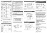
Model Displays Bezel size
BA307E 4 digits 15mm high 96 x 48mm
BA327E 5 digits 11mm high 96 x 48mm
and bargraph.
BA308E 4 digits 34mm high 144 x 72mm
BA328E 5 digits 29mm high 144 x 72mm
and bargraph.
This abbreviated instruction sheet is intended to assist with
installation and commissioning, a comprehensive instruction
manual describing safety certication, system design and
calibration is available from the BEKA sales oce or may be
downloaded from the BEKA website.
All the models have IECEx ATEX and UKEX intrinsic safety
certication for use in ammable gas & dust atmospheres. FM and
cFM approval also permits installation in the USA and Canada.
The certication label, which is located on the top of the instrument
enclosure shows the certicate numbers and the certication
codes. Copies of certicates may be down- loaded from our
website.
Typical certication information label
Special conditions for safe use
The IECEx, ATEX and UKEX certicates have an ‘X’ sux
indicating that special conditions apply for safe use.
WARNING
To avoid an electrostatic charge being generated
instrument enclosure should only be cleaned with a
damp cloth.
Special conditions also apply for use in IIIC conductive dusts -
please see full manual.
2. INSTALLATION
All the models have IP66 front of panel protection but they should
be shielded from direct sunlight and severe weather conditions.
The rear of each indicator has IP20 protection.
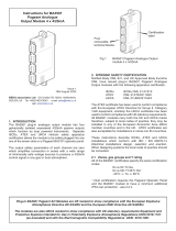
Cut-out dimensions
Recommended for all installations. Mandatory to achieve an IP66
seal between the instrument & the panel
BA307E & BA327E
90 +0.5/-0.0 x 43.5 +0.5/-0.0
BA308E & BA328E
136 +0.5/-0.0 x 66.2 +0.5/-0.0
657.5
48 / 72
96 / 144
+
1 2 3 4
Terminals 2 & 4 are
internally linked for
joining return
4/20mA wire
89 10 1112 13
+-
Alarm 1 Alarm 2
Terminals for
optional alarms
++-
Terminals for
optional backlight
14
--
Separately
powered
Loop powered
Common
Fig 1 cut out dimensions & terminals
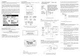
4. Insert panel clamp into recess
and gently pull it onto the dovetail.
Engage screw & turn clockwise
to tighten the clamp, fit the other
clamp(s). Recommended tightening
torque 22cNm (1.95lbf.in) Equivalent
to finger tight plus one half turn.
DO NOT OVERTIGHTEN
BA308E & BA328E require 4 clamps
for IP66 front panel sealing
2. Position
gasket
behind
instrument
bezel
3. Insert
instrument
into the panel
from the front
1. Align foot and body of panel
mounting clamp by turning
screw anticlockwise
Fig 2 Installation procedure
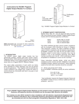
EMC
For specied immunity all wiring should be in screened twisted
pairs, with the screens earthed at one point within the safe area.
2-wire
Tx
Safe areaHazardous area
4/20mA
3 4 2 1 2 channel Zener barrier
28V; 93mA; 300Ω
diode return
Load
Instru-
ment
power
supply
+
0
Fig 3 Typical measurement loop
Scale card
The indicator’s units of measurement are shown on a printed scale
card visible through a window at the right hand side of the display.
The scale card is mounted on a exible strip that is inserted into a
slot at the rear of the instrument as shown below.
I
n
s
e
r
t
Unlock
Lock
Fig 4 Inserting exible strip carrying scale
card into slot at the rear of indicator.
Thus the scale card can easily be changed without removing the
indicator from the panel or opening the instrument enclosure.
New indicators are supplied with a printed scale card showing the
requested units of measurement, if this information is not supplied
when the indicator is ordered a blank card will be tted.
A pack of self-adhesive scale cards printed with common units of
measurement is available as an accessory from BEKA associates.
Custom printed scale cards can also be supplied.
To change a scale card, unclip the protruding end of the exible
strip by gently pushing it upwards and pulling it out of the enclosure.
Peel the existing scale card from the exible strip and replace it with
a new printed card, which should be aligned as shown below. Do
not t a new scale card on top of an existing card.
Align the self-adhesive printed
scale card onto the exible
strip and insert the strip into
the indicator as shown above.
Fig 5 Fitting scale card to exible strip
3. OPERATION
The indicators are controlled via four front panel push buttons. In
the display mode i.e. when the indicator is displaying a process
variable, these push buttons have the following functions:
( While this button is pushed the indicator will display
the input current in mA, or as a percentage of the
instrument span depending upon how the indicator
has been conditioned. When the button is released
the normal display in engineering units will return. The
function of this push button is modied when optional
alarms are tted to the indicator.
& While this button is pushed the indicator will display the
numerical value and analogue bargraph* the indicator
has been calibrated to display with 4mA input. When
released the normal display in engineering units will
return.
* While this button is pushed the indicator will display the
numerical value and analogue bargraph* the indicator
has been calibrated to display with 20mA input. When
released the normal display in engineering units will
return.
) No function in the display mode unless the tare
function is being used.
( + & Indicator displays rmware number followed by
version.
( + * When alarms are tted provides direct access to the
alarm setpoints if the ‘ACSP’ access setpoints in
display mode function has been enabled.
( + ) Provides access to the conguration menu via optional
security code.
* Only the BA327E & BA328E have a bargraph
Align on
these
edges
BA307E
BA327E BA308E
BA328E
Scale
card
Scale
card
Align on
these
edges
Abbreviated Instruction for
BA307E, BA327E, BA308E & BA328E
intrinsically safe panel mounting
loop powered indicators
Issue 6
24th November 2022
BEKA associates Ltd. Old Charlton Rd, Hitchin, Hertfordshire,
web: www.beka.co.uk