1. DESCRIPTION
The BA554E is a eld mounting, general purpose, 4/20mA
rate totaliser primarily intended for use with owmeters. It
simultaneously displays the rate of ow (4/20mA current) and
the total ow in engineering units on separate displays. It is
loop powered but only introduces a 1.2V drop into the loop.
This abbreviated instruction sheet is intended to assist with
installation and commissioning, a comprehensive instruction
manual describing system design and conguration is available
from the BEKA sales oce or may be downloaded from our
webste.
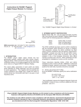
2. INSTALLATION
The BA554E rate totaliser has a robust IP66 glass reinforced
polyester (GRP) enclosures incorporating an armoured glass
window and stainless steel ttings. It is suitable for exterior
mounting in most industrial environments.
It is surface mounting, but may be pipe mounted using one of
the accessory kits.
Fig 1 shows the installation procedure.
The rate totaliser’s earth terminal is connected to the carbon
loaded GRP enclosure. If this enclosure is not bolted to
an earthed post or structure, the earth terminal should be
connected to the plant potential equalising conductor.
A bonding plate is provided to ensure electrical continuity
between the three conduit / cable entries.
Terminals 8, 9, 10 & 11 are only ttted when the rate totaliser
includes optional alarms. See full manual for details.
Terminals 12, 13 & 14 are only tted when the rate totaliser
includes an optional backlight. See full manual for details.
EMC
The BA554E complies with the European EMC Directive
2004/108/EC. For specied immunity all wiring should be in
screened twisted pairs, with the screens earthed in the safe area.
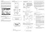
DISPLAY
2-wire
Tx
4/20mA Load
3
Reset
RS2
RS1
4 2 1
Instrument
power
supply
+
0
6 5
Fig 3 Typical measurement loop
Units of measurement & tag number
The BA554E has an escutcheon around the liquid crystal
display which can be supplied printed with any units of
measurement and tag information specied when the
instrument was ordered. If no information was supplied a
blank escutcheon will be tted but legends may be added
on-site via an embossed strip, dry transfer or a permanent
marker. Custom printed escutcheons are available from
BEKA as an accessory which should be tted on top of the
blank escutcheon. Do not remove the blank escutcheon.
To gain access to the escutcheon remove the terminal cover by
unscrewing the two ‘A’ screws which will reveal two concealed
‘D’ screws. If the instrument is tted with an external keypad,
also unscrew the two ‘C’ screws securing the keypad and
un-plug the ve way connector. Finally unscrew all four ‘D’
screws and carefully lift o the front of the instrument. Add
the required legend to the escutcheon, or stick a new printed
self-adhesive escutcheon on top of the existing escutcheon.
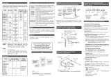
3. OPERATION
The BA554E is controlled and congured via four push
buttons located behind the instrument control cover, or via an
optional keypad on the outside of the control cover. In the
display mode i.e. when the instrument is totalising, these push
buttons have the following functions:
P Displays input current in mA or as a percentage of
span. (congurable function)
Modied when optional alarms are tted.
▼ Shows rate display calibration at 4mA input
▲ Shows rate display calibration at 20mA input
E Shows time since instrument was powered or total
display was reset.
E+▼ Grand total
displays least signicant 8 digits
E+▲ Grand total
displays most signicant 8 digits
▼+▲ Resets total display
(congurable function)
P+▼ Shows rmware version
P+▲ Optional alarm setpoint access
P+E Access to conguration menu
The BA554E is CE marked to show compliance with the
EMC Directive 2004/108/EC.
Abbreviated Instructions for
BA554E general purpose eld
mounting loop powered rate totaliser
Issue 2
10th March 2014
BEKA associates Ltd. Old Charlton Rd, Hitchin, Hertfordshire,
SG5 2DA, UK Tel: +44(0)1462 438301 Fax: +44(0)1462 453971
E
P
TAG NUMBER SCALE
B
D
DB
D
D
Step 3 and 4
Remove the temporary
hole plug and install
appropriate IP rated cable
gland or conduit fitting and
terminate field wiring.
Replace the terminal cover
and tighten the two 'A' screws.
Step 2
Secure the instrument
to a flat surface with M6
screws through the
two 'B' holes.
Alternatively use a pipe
mounting kit.
Step 1
Remove the terminal
cover by unscrewing
the two 'A' screws
B
D
DB
D
D
C
A
C
A
DISPLAY
DISPLAY
DISPLAY
A
A
C
C
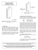
Fig 2 Dimensions and terminal connections
DISPLAY
91
141
212
Separate
terminal
compartment
117
72
Two M6 clearance holes
for surface mounting
M20 x 1.5 tapped.
Supplied with two IP66 stopping
plugs & one temporary hole plug.
Terminals 2 & 4
internally linked
for joining return
4/20mA wire.
Terminials 5 & 6
internally linked
for joining cable
screens
Control
Cover
1110914 81312
4321
65E
++--+
+ -
Terminals for
optional alarm,
see full manual
Terminals for optional
backlight, see full manual
Separately
powered
Loop powered
Common
4/20mA input
RS2
RS1
RS2
Reset
RS1