Anttron DTVDM2 Installation guide

Category
Signal converters
Type
Installation guide

This manual is also suitable for

Anttron DTVDM2 is a versatile device that can receive a transport stream, filter the programs, and modulate them in DVBT on two adjacent channels. With its built-in attenuator, you can adjust the output level from 0 dB (max. output) to -20 dB, making it suitable for various applications. The modulator supports multiple modulation parameters, allowing you to customize the output signal to meet your specific requirements.

Anttron DTVDM2 is a versatile device that can receive a transport stream, filter the programs, and modulate them in DVBT on two adjacent channels. With its built-in attenuator, you can adjust the output level from 0 dB (max. output) to -20 dB, making it suitable for various applications. The modulator supports multiple modulation parameters, allowing you to customize the output signal to meet your specific requirements.

DTVDM2-DTVDM4
PROGRAMMING AND INSTALLATION GUIDE V1.0
Twin and quad DVBT modulators for DTVRack
This manual is also applicable for DTVDM2 and DTVDM4 modules in the com-
pact headends, TRM3x2, TRM3x2CI and TRM6x4, TM300, TM400 etc....
USER MANUAL
PAGE 2
ANTTRON ©2013
DTVDM2/4
C1
C2
A1
DVBT output
DVBT Bypass
Modulator status LED : GREEN if OK / RED if not OK
DTVDM2/4 : this modules perform the following function in the DTVRack
a) It receives the transport stream from the ‘backplane’ in the DTVRack.
b) The programs in these transportstream or then ltered and modulated in
DVBT on the 2 (DTVDM2) or 4 (DTVDM4) available DVBT channels. The 2 or 4
DVBT channels are adjacent.
c) The output frequency and modulation type can be choosen. LCN and HD
LCN channel numbers can be assigned to the programs. Also the output level
of the modulator can be adjusted.
1. Accessing the parameters of a DTVDM2/DTVDM4 module.
When in DTVIface, click on a DTVDM2 or DTVDM4 symbol to get access to the para-
meters of the modulator module.
Depending if a DTVDM2 or DTVDM4 module is chosen, following window may appear.
a) a module DTVDM2 is selected
USER MANUAL
PAGE 3
ANTTRON ©2013
DTVDM2/4
USER MANUAL
PAGE 4
ANTTRON ©2013
DTVDM2/4
b) a module DTVDM4 is selected
2. Setting the parameters of the modulator
For the modulator following parameters can
be set.
N.I.T
Version : enter the NIT version
ONID : enter the decimal code for the Orig-
inal Network ID. The original network ID is
the country where you are located.
NID: enter the network ID.
Network Name : enter the network name.
Under the N.I.T. parameters you will nd the output frequency of the modulator. As the DTVDM2, DT-
VDM4 have adjacent output channels, you can only set the output frequency of the rst channel.
The frequency of the other channels is automatically adjusted, so you can not change the output fre-
quency of the second channel (for DTVDM2) or the other 3 channels (for DTVDM4).
T.S. Id : for each channel a T.S.Id should be assigned.
Modulation parameters : furthermore, you can set the modulation parameters for the modulator.
Please select the constellation, Bandwidth, F.E.C and Guard Interval.
Output level of the modulator : an internal attenuator allows to lower the output level of the modu-
lator. The attenuator can be adjusted between 0 dB (max. output) and -20 dB.
USER MANUAL
PAGE 5
ANTTRON ©2013
DTVDM2/4
Some remarks on setting the N.I.T parameters and T.S. Id. :
When you make a headend you will probably have more then 1 modulator in your system. In order to
keep consistency throughout your complete headend, please follow these guidelines :
a) For your complete headend make sure that the N.I.T. (version / ONID / NID / Network Name) are
IDENTICAL throughout the entire system.
b) For your complete headend make sure that all T.S. Id. (Transport Stream ID) are UNIQUE. Every
output channel should have a unique ID in the system. Make sure that an T.S.Id. does not appear
more than once in the system.
3 - Adding services (programs) to the modulator:
In the list of programs, you will nd two (for DTVDM2) or four (for DTVDM4) columns with a GREEN +
symbol or RED - symbol.
The columns indicate the output channels of the modulator (column 1 is rst channel, column 2 is
second channel (column 3 and colum 4 are third and fourth channel for DTVDM4 modulator).
If a green + symbol appears besides a certain program, this means that this program is added to that
specic channel in the modulator.
The status can be changed by double-clicking the activation symbol besides the requested program.
In the most right colums you can add a LCN number or HDLCN number for channel numbering.
What means HD LCN ?
In some systems, it can happen that you want to broadcast at the same time the SD (Standard De-
nition) version of a progam and the HD (High Denition) version of a program.
With HD LCN numbering, you can force HD Television sets to follow the HD LCN numbering and SD
Television sets to follow the LCN numbering for those programs which are transmistted in double.
Some practical example :
Suppose you have in your system the program ‘Das Erste’ in SD version and in HD version. Applica-
tion of HD LCN would then be :
Das Erste LCN : 5 HDLCN : 55
Das Erste HD LCN : 55 HDLCN : 5
Television sets with HD tuner will now put Das Erste HD on number 5 and Das Erste on 55.
Television sets without HD tuner will put Das Erste HD on number 55 and Das Erste on 5.
USER MANUAL
PAGE 6
ANTTRON ©2013
DTVDM2/4
4 - Additional information :
In the window of the DTVDM2/4 modulator you will nd some usefull additional information.
To the left of N.I.T information, you will nd a ‘terrestrial symbol’.
The number under this symbol, gives you the total occupied bandwidth of the modulator.
Off course, this number should not exceed the maximum available bandwidth of the modulator.
The maximum available bandwidth is calculated on the maximum available bandwidth per channel x
the number of channels. The maximum available bandwidh per channel is depending on the modulation
parameters (Constellation / Bandwidth / F.EC./Guard Interval). You will nd an overview of the maxi-
mum available bandwidh in function of the modulation parameters later in this manual.
For instance for a DTVDM4 modulator, the maximum available bandwidth is 4 x 31.6 Mbit/s = approx.
125 Mbit/s. For a DTVDM2, this is half (2 x 31.6).
The occupied bandwidth of each channel in the modulator is showed by bargraphs in the modulator
window.
The occupied bandwidth will increase as the number of programs added to that channel is increased.
It also depends on the bandwidh of each individual program.
Please check, not to overload a channel as this will lead to ‘defects’ in the programs.
Please note that when no services (programs) are added to an output channel, the channel will be not
active. This also means that you can decide for the DTVDM4 to act as a single, twin , triple or quad
modulator, or for a DTVDM2 to use it as a single channel modulator.
If you change satellite parameters, the previously dened services for the modulator, will appear as
question marks in the list. (see gure below).
Please remove these services by double clicking the activation button . No services preceeded with a
question mark should be in list.
USER MANUAL
PAGE 7
ANTTRON ©2013
DTVDM2/4
5. Relative bandwidth of a program in the transport stream
In the bottom of the window, you will nd a bar divided in a number of blocks.
The number of blocks is equal to the number of programs added to the modulator.
The width of the blocks is in direct relation with the bandwidth of the program.
For instance, in below window, when on program ProSieben, a certain block in the bottom turns bleu.
This blue block gives you a relative idea of the occupied bandwidth of this program in the transport
stream.
This information can be helpful in assigning the different programs to the different channels on the
modulator.
DVBT output (adjacent)
(DTVDM2 = 2 channels)
(DTVDM4 = 4 channels)
Maximum output > 95 dBµV
Aenuaon 0 - 20 dB
Inseron loss < 2 dB
Output frequency 47-862 MHz
Constellaon QPSK/16QAM/64QAM
FEC 1/2, 2/3, 3/4, 5/9, 7/8
Gard interval 1/4, 1/8, 1/16, 1/32
Mode 2K
6 - Technical specications
USER MANUAL
PAGE 8
ANTTRON ©2013
DTVDM2/4
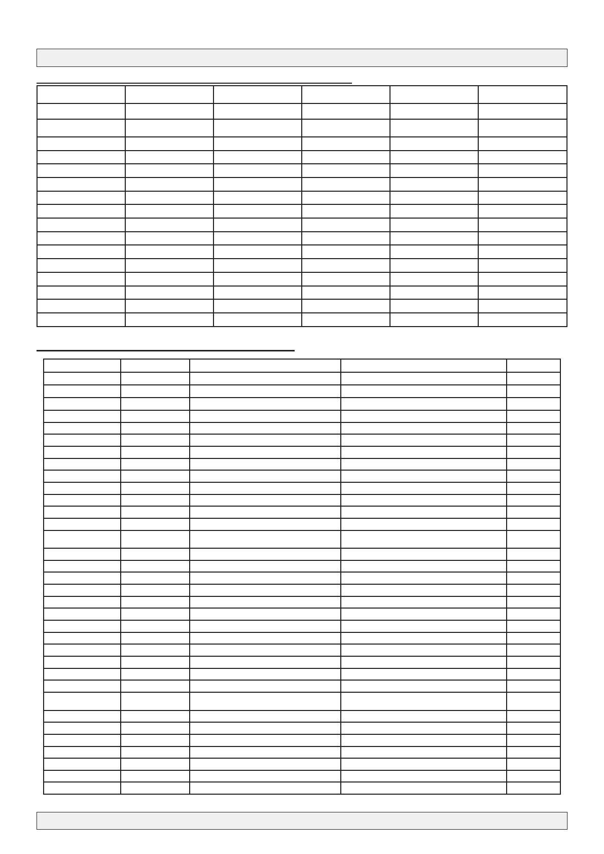
Annex B : ONID : Original Network ID
Original Network ID Original Network ID
Range Original_Network_Name Original_Network_Operator
Start (HEX) End (HEX)
…..
0x2024 0x2024 Australian Digital Terrestrial Television Australian Broadcasting Authority
0x2028 0x2028 Austrian Digital Terrestrial Television ORS - Austrian Broadcasting Services 8232
0x2038 0x2038 Belgian Digital Terrestrial Television BIPT 8248
0x209E 0x209E Taiwanese Digital Terrestrial Television Directorate General of Telecommunications
0x20CB 0x20CB Czech Republic Digital Terrestrial Television Czech Digital Group
0x20D0 0x20D0 Danish Digital Terrestrial Television National Telecom Agency Denmark
0x20E9 0x20E9 Estonian Digital Terrestrial Television Estonian National Communications Board
0x20F6 0x20F6 Finnish Digital Terrestrial Television Telecommunicatoins Administratoin Centre, Finland 8438
0x20FA 0x20FA French Digital Terrestrial Television Conseil Superieur de l'AudioVisuel 8442
0x2114 0x2114 German Digital Terrestrial Television IRT on behalf of the German DVB-T broadcasts 8468
0x2168 0x2168 Digital Terrestrial Network of Indonesia Ministry of Communication and Information Technology of
the Republic of Indonesia
0x2174 0x2174 Irish Digital Terrestrial Television Irish Telecommunications Regulator
0x2178 0x2178 Israeli Digital Terrestrial Television BEZEQ (The Israel Telecommunication Corp Ltd .)
0x217C 0x217C Italian Digital Terrestrial Television 8572
0x21AC 0x21AC DTT - Latvian Digital Terrestrial Television Electronic Communications Ofce
0x2210 0x2210 Netherlands Digital Terrestrial Television Nozema 8720
0x222A 0x222A DTT - New Zealand Digial Terrestrial Television TVNZ on behalf of Freeview New Zealand
0x2242 0x2242 Norwegian Digital Terrestrial Television Norwegian Regulator
0x2260 0x2260 DTT - Philippines Digital Terrestrial Television NTA (porivionally ABS-CBN)
0x2268 0x2268 DTT Poland Ofce of Electronic Communications
0x22BE 0x22BE Singapore Digital Terrestrial Television Singapore Broadcasting Authority
0x22BF 0x22BF Telecommunications ofce of the Slovak republic Telecommunications ofce of the Slovak republic
0x22C1 0x22C1 DTT - Slovenian Digital Terrestrial Television APEK
0x22C6 0x22C6 DTT - South African Digital Terrestrial Television South African Broadcasting Corporation Ltd. (SABC), pending
formation of "DZONGA"
0x22C7 0x22C7 DTT- Hungarian Digital Terrestrial Television National Communications Authority, Hungary
0x22C8 0x22C8 DTT- Portugal Digital Terrestrial Television ANACOM- National Communications Authority
0x22D4 0x22D4 Spanish Digital Terrestrial Television “Spanish Broadcasting Regulator 8916
0x22F1 0x22F1 Swedish Digital Terrestrial Television “Swedish Broadcasting Regulator ” 8945
0x22F4 0x22F4 Swiss Digital Terrestrial Television OFCOM 8948
0x233A 0x233A UK Digital Terrestrial Television Independent Television Commission
…..
Annex A : Constellation and maximum bit rate
Modulation Code Rate Guard 1/4 Guard 1/8 Guard 1/16 Guard 1/32
Mb/s Mb/s Mb/s Mb/s
QPSK 1/2 4.976471 5.529412 5.854671 6.032086
2/3 6.635294 7.372549 7.806228 8.042781
3/4 7.464706 8.294118 8.782007 9.048128
5/6 8.294118 9.215686 9.757785 10.05348
7/8 8.708824 9.676471 10.24567 10.55617
16 QAM 1/2 9.952941 11.05882 11.709341 12.06417
2/3 13.27059 14.74510 15.61246 16.08556
3/4 14.92941 16.58824 17.56401 18.09626
5/6 16.58824 18.43137 19.51557 20.10695
7/8 17.41765 19.35294 20.49135 21.11230
64 QAM 1/2 14.92941 16.58824 17.56401 18.0926
2/3 19.90588 22.11765 23.41869 24.12834
3/4 22.39412 24.88235 26.34602 27.14439
5/6 24.88235 27.64706 29.27336 30.16043
7/8 26.12647 29.02941 29.27336 31.66845
  • Page 1 1
  • Page 2 2
  • Page 3 3
  • Page 4 4
  • Page 5 5
  • Page 6 6
  • Page 7 7
  • Page 8 8

Anttron DTVDM2 Installation guide

Category
Signal converters
Type
Installation guide
This manual is also suitable for

Anttron DTVDM2 is a versatile device that can receive a transport stream, filter the programs, and modulate them in DVBT on two adjacent channels. With its built-in attenuator, you can adjust the output level from 0 dB (max. output) to -20 dB, making it suitable for various applications. The modulator supports multiple modulation parameters, allowing you to customize the output signal to meet your specific requirements.

Ask a question and I''ll find the answer in the document

Finding information in a document is now easier with AI