SLIM 62 INSTALLATION INSTRUCTIONS
Thank you for buying RAB lighting xtures. Our goal is to design the best quality products to get the job done right. We’d like to hear your comments.
Call the Marketing Department at 888-RAB-1000 or email: marketing@rabweb.com
TM
SLIM56 WIRE GAURD
RAB LIGHTING
3/22/2013
SLIM56 POLYSHIELD
RAB LIGHTING
3/22/2013
CLEANING & MAINTENANCE
CAUTION: Be sure xture temperature is cool enough to
touch. Do not clean or maintain while xture is energized.
1. Clean glass lens & xture with non-abrasive glass cleaning
solution.
2. Do not open xture to clean the LED. Do not touch the LED.
TROUBLESHOOTING
1. Check that the line voltage at xture is correct. Refer to
wiring directions.
2. Is the xture grounded properly?
3. Be sure the photocell, if used, is functioning properly.
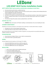
GUARD/ SHIELD INSTALLATION
1. Remove left and right Cover Plates as in gure 1 and
discard.
2. Mount wire guard and/ or poly shield with (4) #8-32 x 1/2”
Stainless Steel Screws. Screws are provided with the
accessory.
Stainless Steel Screws (4)
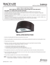
FULL CUTOFF/ GUARD/ SHIELD
INSTALLATION
1. Remove (4) Stainless Steel Screws from the Full Cuto
Hood.
2. Mount wire guard and/ or poly shield over the full cuto
hood with (4) #8-32 x 1/2” Stainless Steel Screws as shown
in gure 2. Screws are provided with the accessory.
Stainless Steel
Screws
Figure 1
Stainless Steel
Screws
Figure 2
Cover Plate
Full Cuto Hood
Note: Guard and shield may be used together.
Note: Guard, shield and full cuto hood may be used together
with (4) #8-32 x 3/4” stainless steel screws (supplied by others).
Stainless Steel Screws (4)
Note: These instructions do not cover all details or variations in equipment
nor do they provide for every possible situation during installation
operation or maintenance.
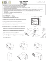
PHOTOCELL INSTALLATION
Photocell may be installed in the eld. Apply weatherproof
silicone sealant to all plugs and unused conduit entries.
1. Remove close up plug on top of the wall mounting box.
2. Install photocell and wire as per diagram.
3. Use photocell rated for your supply voltage.
“COM”
PHOTOCELL
WP2FC
LIGHT
FIXTURE
BLACK
WHITE
PHOTOCELL
SLIM62-IN 1016
Easy Installation & Product Help
Tech Help Line
Call our experts 888 RAB-1000
©2016 RAB LIGHTING Inc.
Northvale, New Jersey 07647 USA
rabweb.com
Visit our website for product info
email
Answered promptly sales@rabweb.com