Rev-A-Shelf 5LB-1230SSBL-118 Operating instructions

Type
Operating instructions
INSTALLATION INSTRUCTIONS: 5LB SERIES LEGRABOX WASTE CONTAINER
12400 Earl Jones Way
Louisville, KY 40299
rev-a-shelf.com
Customer Service: 800-626-1126
5LB SERIES LEGRABOX WASTE CONTAINER PULLOUTS
TOOLS REQUIRED:
30 MIN
ESTIMATED ASSEMBLY TIME:
CARE AND MAINTENANCE:
Clean with a damp cloth and
wipe parts dry.
IMPORTANT NOTE - OPENING DIMENSIONS ARE CRUCIAL
SINGLE 35/50 QT. WASTE CONTAINER UNITS ARE TO BE INSTALLED INTO
CABINETS WITH A 13.5” OPENING. DOUBLE 35/50 QT. WASTE CONTAINER UNITS
ARE TO BE INSTALLED INTO CABINETS WITH A 16.5” OPENING. SINGLE 30 QT.
WASTE CONTAINER UNITS ARE TO BE INSTALLED INTO CABINETS WITH A 10.5”
OPENING.
I-5LB-1217
#2
Parts List
No. Description Qty
1 Assembled LEGRABOX 1
2 Waste Container Divider Insert 1
3 Waste Container(s) 1-2
4 Waste Container Lid 1
5 Door Mount Brackets 2
6 RV Door Mount Screw Packs 2
7 5LB Slide Mount Screw Packs 1
8 Rev-A-Shelf Logo Cover Caps 2
T20
1
5 6
7
8
2
4
3
x6 PER PACK
#6x 1/2”
#8x 1/2”
x8 PER PACK
WATCH VIDEO TUTORIALS OF
PRODUCT INSTALLATIONS
WWW.REV-A-SHELF.COM/VIDEOS
Customer Service: 800-626-1126 | rev-a-shelf.com
2
Use the measurements from
Figure 1 to mark the slide
mounting hole locations.
(recommended with an awl and
rubber mallet).
NOTE: If installing into a face
frame cabinet, the cabinet
side walls will need to be
made ush with the face
frame using a scab board.
STEP 1
Install slides in your cabinet
using #8 x 1/2” screws found
in 5LB slide mount screw pack
(See Fig 2).
STEP 2
Place the frame on the slide at
an angle and then lay at (See
Fig 3.1). Push back until you
hear a “click” (See Fig 3.2).
STEP 3
FIGURE 1
FIGURE 2
FIGURE 3.1 FIGURE 3.2
#2
ALL HOLES ARE
1-1/2” (38 mm)
FROM CABINET
FLOOR
INSERT AT AN ANGLE
PUSH UNTIL YOU HEAR A ”CLICK”
1-15/32”
(37 mm)
1-1/2”
(38 mm)
2-23/32”
(69 mm)
14-1/16” (357 mm)
HOLE
LOCATIONS
NOTE: THE BELOW STEPS SHOW INSTALLATION INTO A FRAMELESS CABINET. IF INSTALLING INTO
A FACE FRAME CABINET, YOUR CABINET SIDE WALLS WILL NEED TO BE MADE FLUSH WITH THE
FACE FRAME USING A SCAB BOARD. CABINET OPENING DIMENSIONS REMAIN CRUCIAL.
11-17/32” (293 mm)
INSTALLATION INSTRUCTIONS: 5LB SERIES LEGRABOX WASTE CONTAINER
3
Use the measurements from
Figure 5 to mark the door
mounting hole locations
(recommended with an awl and
rubber mallet).
STEP 5
Place the Rev-A-Shelf logo
caps on both sides of the
LEGRABOX (See Fig 4).
STEP 4
Install the door brackets to the
door with the #6 x 1/2” screws
included with the RV Door
Mount screw pack
(See Fig 6).
NOTE: Make sure not to drill
through the door.
NOTE: Each pack contains
(2) extra screws. Discard any
extras you don’t need.
STEP 6
Align the door brackets to
the locks on the front of the
LEGRABOX frame and push
until you hear a “click” sound
(See Fig 7).
STEP 7
FIGURE 5
FIGURE 6
FIGURE 7
#2
2” (51 mm) + Overlay
9-13/32” (239 mm) - Single 30 qt. container width
12-13/32” (315 mm) - Single 35/50 qt. container width
15-13/32” (391 mm) - Double 35/50 qt. container width
1-1/4” (32 mm)
9/16” (14mm) + Overlay
3-25/32” (96 mm)
FIGURE 8
REMOVE CAP
REMOVE CAP
If your LEGRABOX needs to
be adjusted to t the door
properly, rst remove the
cover caps (See Fig 8).
STEP 8
Finding The Overlay
The overlay equals the door
height minus the cabinet
opening height divided by 2.
For example, if a door is 24”
(610 mm) tall, and the cabinet
opening is 23” (584 mm) tall:
24-23=1
1÷2 = .5
The overlay = 1/2” (13 mm)
FIGURE 4
1-1/4” (32 mm)
1-1/4” (32 mm)
9/16” (14 mm) + Overlay
2” (51 mm) + Overlay
1-1/4” (32 mm)
3-25/32” (96 mm)
1-1/4” (32 mm)
1-1/4” (32 mm)
Customer Service: 800-626-1126 | rev-a-shelf.com
4
12400 Earl Jones Way
Louisville, KY 40299
rev-a-shelf.com
Customer Service: 800-626-1126
For inward/outward tilt
adjustment, height adjustment
and side adjustment of
the LEGRABOX, use the
corresponding adjustment
locations (See Fig 9).
STEP 9
To remove the LEGRABOX,
pull the drawer out, locate the
triggers on the slides (See Fig
10), and squeeze them. Once
the slides have disengaged,
the LEGRABOX can be
removed.
To remove the door, turn the
adjustment screw on both
sides of the drawer to release
the lock (See Fig 11.1). Then
lift the door front away from
the LEGRABOX box
(See Fig 11.2).
REMOVING THE LEGRABOX
REMOVING THE DOOR
FIGURE 9
FIGURE 10
FIGURE 11.1 FIGURE 11.2
T20
T20
HEIGHT ADJUSTMENT
TILT ADJUSTMENT
SIDE ADJUSTMENT
Ask about our LEGRABOX TIP-ON Kit, can be retrotted to
current/existing models (sold separately).
Customer Service: 800-626-1126 | rev-a-shelf.com
6
Use las medidas (ver ma gura 1)
para marcar las ubicaciones de los
oricios del montaje del deslizante. Se
recomienda usar una lezna y un mazo
de goma para este paso.
NOTA: Si usted está instalando dentro
de un gabinete con marco, usted
necesitará rebajar la pared lateral del
gabinete para que esté al ras con la
apertura de la cara del marco.
Utilisez les mesures (voir l’Illustration 1)
pour marquer les emplacements des
trous de montage de la coulisse. Il est
recommandé d’utiliser un maillet en
caoutchouc pour cette étape.
REMARQUE: Si vous installez dans
une armoire avec cadrage avant, vous
aurez besoin de renforcer la paroi
latérale de l’armoire pour qu’elle soit à
ras de l’ouverture du cadrage avant.
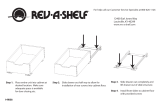
PASO 1
ÉTAPE 1
PASO 2
ÉTAPE 2
PASO 3
ÉTAPE 3
Instale los deslizantes en su gabinete
usando los tornillos que se encuentran
en el paquete 5LB de tornillos de
montaje del deslizante del #8x1/2”
(ver la gura 2).
Installez les coulisses dans votre armoire
avec les vis # 8x1/2” trouvées dans le
paquet 5LB de vis de montage de la
coulisse (voir l’Illustration 2).
Coloque el marco en el deslizante en un
ángulo (ver la gura 3.1). Empuje hacia
atrás hasta que escuche el sonido de un
“click” (ver la gura 3.2).
Placez le cadre sur la coulisse en
l’inclinant (voir l’Illustration 3.1). Poussez
jusqu’à ce que vous entendiez un “clic”
(voir l’Illustration 3.2).
FIGURA 1
ILLUSTRATION 1
FIGURA 2
ILLUSTRATION 2
FIGURA 3.1
ILLUSTRATION 3.1
FIGURA 3.2
ILLUSTRATION 3.2
#2
TODOS LOS
ORIFICIOS SON
DE 1-1/2” (38MM)
DESDE EL PISO DEL
GABINETE
TOUS LES TROUS
SONT À 1-1/2” (38MM)
DU PLANCHER DE
L’ARMOIRE
INSERTE EN UN ÁNGULO
INSÉREZ EN INCLINANT
EMPUJE HASTA QUE ESCUCHE UN “CLICK”
POUSSEZ JUSQU’À CE QUE VOUS ENTENDIEZ UN “CLIC”
UBICACIONES DE AGUJEROS
EMPLACEMENTS DES TROUS
NOTA: LOS SIGUIENTES PASOS MUESTRAN LA INSTALACIÓN DENTRO DE UN GABINETE SIN MARCO. SI ESTÁ INSTALANDO EN UN
GABINETE CON MARCO, LAS PAREDES LATERALES DE SU GABINETE NECESITARÁN ESTAR AL RAZ CON LA CARA DEL MARCO USANDO
UNA TABLA. LAS DIMENSIONES DE LA APERTURA DEL GABINETE CONTINÚAN SIENDO CRÍTICAS.
REMARQUE: LES ÉTAPES CI-DESSUS MONTRENT UNE INSTALLATION DANS UNE ARMOIRE SANS CADRE. SI L’INSTALLATION SE FAIT DANS UNE ARMOIRE AVEC
CADRAGE AVANT, LES PAROIS LATÉRALES DE VOTRE ARMOIRE DOIVENT ÊTRE À RAS DU CADRAGE AVANT EN UTILISANT UN RENFORCEMENT.
LES DIMENSIONS DE L’OUVERTURE DE L’ARMOIRE SONT ESSENTIELLES.
1-15/32”
(37 mm)
1-1/2”
(38 mm)
2-23/32”
(69 mm)
11-17/32” (293 mm)
14-1/16” (357 MM)
  • Page 1 1
  • Page 2 2
  • Page 3 3
  • Page 4 4
  • Page 5 5
  • Page 6 6
  • Page 7 7
  • Page 8 8

Rev-A-Shelf 5LB-1230SSBL-118 Operating instructions

Type
Operating instructions

Ask a question and I''ll find the answer in the document

Finding information in a document is now easier with AI