INSTALLATION INSTRUCTIONS: 53WC SERIES PULLOUT WASTE CONTAINER 3
FIGURE 4B
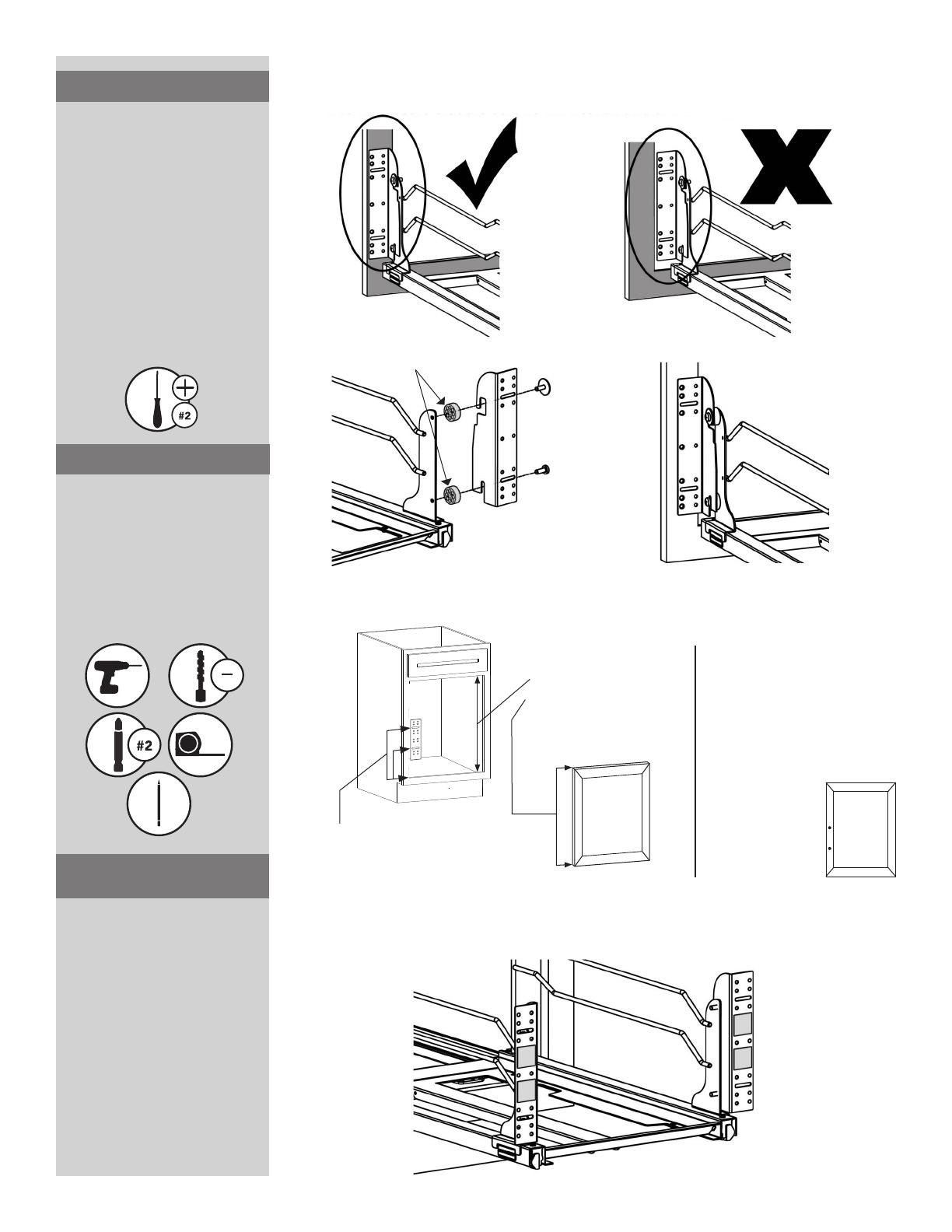
FIGURE 4C
FIGURE 5B
Each cabinet door is different,
so make sure the door
brackets line up with the thick
portion of the cabinet door
(See Figure 4B). This will ensure
that the screws will not go
completely through the door.
NOTE: Plastic spacers are
provided if the door brackets
need to be extended further
to reach the thick portion of
the door (See Figure 4C). If so,
you will need to replace the
5
/
8
”
bolts (part number 12) with the
1
1
/
4
” bolts (part number 13).
STEP 4B
Apply double stick tape to the
door brackets. Attach cabinet
door to the brackets while
trying to keep door level. Don’t
worry if it is off a little. This can
all be adjusted. Double stick
tape will hold the door in place
while you screw the brackets to
cabinet door. (See Figure 5B)
NOTE: Although this method
is the quickest and easiest
method to attach the door, it
does limit adjustability since the
door will become adhered to
the brackets
STEP 5B
ALTERNATE METHOD
1) Make sure that your unit is securely installed into your cabinet. Remove the cabinet door and
hinges to begin to mount your door.
2) Using the (4) provided screws and nuts, attach the L-Brackets to your slide.
Note: Depending on your particular basket design L-Bracket will mount on either inside or
outside of wire.
3a) Attach the door brackets to the outside of the L-brackets using the (4) provided screws.
Inside wire shown
4)
Aplique cinta de doble lado a los soportes de la puerta. Sujete la puerta del gabinete a los
soportes mientras trata de mantener la puerta a nivel. No se preocupe si la puerta se mueve un
poco, esto puede ser ajustado. La cinta de doble lado sujetara la puerta en su lugar mientras usted
atornilla los soportes a la puerta del gabinete.
Mettez du ruban adhésif double sur les supports de porte. Fixez la porte de l’armoire aux
supports tout en essayant de maintenir la porte à niveau. Ne vous inquiétez pas si elle n’est pas
tout à fait à niveau, tout cela peut être ajusté. Le ruban adhésif double tiendra la porte en place
pendant que vous vissez les supports sur la porte de l’armoire.
3c) Se proveen espaciadores de plástico si es que los soportes de la puerta necesitan ser extendi-
dos para alcanzar la porción gruesa de la puerta.
Des espaceurs en plastique sont fournis si les supports de porte doivent être étendus plus loin
pour atteindre la partie épaisse de la porte.
3b) Cada puerta de gabinete es diferente, pero asegúrese de que el soporte de la puerta se alinea
con la porción gruesa de la puerta del gabinete. Esto asegurará que los tornillos no se atraviesen ni
dañen su puerta.
Chaque porte d’armoire est diérente, mais assurez-vous que le support de porte s’aligne avec
la partie épaisse de la porte de l’armoire. Cela permettra d’assurer que les vis ne vont pas passer
à travers et endommager votre porte.
Measure Opening Height ________
Measure Door Height ________
Height Difference ________
Divide Difference by 2 ________
Mark screw locations
on your door and
pre-drill. Be careful
not to drill through the
cabinet door.
If your door is larger than cabinet
opening, add the divided difference
you found in step 2 to the
measurements in step 1. If your door is
smaller, subtract the divided difference
from the measurements in step 1.
Top Measurement ________
Bottom Measurement ________
Measure from frame to top bracket slot ________
Measure from frame to bottom bracket slot ________
FIGURE 5A
1.
2.
3.
Refer to Figure 5A to
determine door mounting
hole locations. Transfer these
dimensions to your door from
the bottom and mark the
hole locations. Pre-drill these
holes on the back side of your
cabinet door, making sure not
to drill through the door.
STEP 5A
3
32
PART NUMBER 15


