Extron DSC HD-HD 4K A User manual

Category
Video converters
Type
User manual

This manual is also suitable for

1
IMPORTANT:
Go to www.extron.com for the complete
user guide,
installation instructions,
and
specifications bef
ore connecting the
pr
oduct to the po
wer source.
DSC HD-HD 4K A Setup Guide
The Extron DSC HD-HD 4K A is a high performance, HDCP 1.4 and 2.2 compliant scaler capable of processing HDMI resolutions
up to 4K @ 30 Hz with full 4:4:4 signal processing and 4K @ 60 Hz with 4:2:0. It features HDMI 1.4 and 2.0 connections that
support data rates up to 8.91 Gbps. This setup guide provides step-by-step instructions for an experienced user to set up and
configure the DSC HD-HD 4K A. It also describes basic operations using front panel controls, the OSD menu system, and
Simple Instruction Set (SIS
) commands.
Installation
ATTENTION:
Installation and service must be performed by authorized personnel only.
L’installation et l’entretien doivent être effectués par le personnel autorisé uniquement.
NOTE: For full installation, configuration, menus, connector wiring, and operation details, see the DSC HD-HD 4K A Series
User Guide, available at www.extron.com.
Rear Panel Features
RS -232
RESET
LAN
AUDIO IN
REMOTE
AUDIO OUT
50-60 Hz
100-240VAC ~ 0.7 A MAX
DSC HD-HD 4K A
LR
LR
Tx Rx G
AA
GG
DD
FF
HDMI
INPUT
HDMI
OUTPUT
BB
CC
HH
II
EE
A
AC power connector
D
Analog audio input connector
G
Remote RS-232 connector
B
HDMI input connector
E
Analog audio output connector
H
Reset LED
C
HDMI output connector
F
Ethernet LAN connector
I
Reset button
Figure 1. DSC HD-HD 4K A Rear Panel
Setup Overview
1. Disconnect power — Turn off or disconnect all equipment power sources.
2. Mount the unit (optional) — Mount the DSC HD-HD 4K HD A either in a rack using shelf mounting bracket kits (available
at www.extron.com) or under furniture using furniture mounting brackets (see the instructions provided with the kit).
Alternatively, attach the four provided rubber feet at the corners of the unit and place it on a table top.
3. Connect the HDMI video input and output — Connect an HDMI video source to the HDMI input connector (
B
) and a
display to the HDMI output (
C
)
connector. Secure each HDMI device to the connector with a provided LockIt
®
bracket.
4. Connect an audio input device (optional) — Connect
an analog audio source to the 5-pole captive screw Audio
In connector (
D
) to embed balanced or unbalanced
analog audio in the HDMI output signal.
5. Connect an audio output device (optional)
Connect an audio output device to the 5-pole captive
screw Audio Out connector (
E
) for analog audio output.
6. Connect a control device — For remote control,
connect a computer or control system to any of these ports:
Remote RS-232 — This 3-pole captive screw RS-232 connector (
G
) enables serial control via SIS
commands. RS-232 protocol for this port is 9600 baud, 1 stop bit, no parity, 8 data bits, and no ow control.
USB — This front panel USB mini-B port (See figure 2,
B
, on the next page) enables conguration and
control via SIS commands or the Extron PCS Conguration software.
LAN — This RJ-45 Ethernet jack (
F
) connects the unit to a network, enabling you to congure the DSC via SIS
commands, PCS, or the device internal web page.
Unbalanced Stereo Input
Balanced Stereo Input
Tip
Ring
Tip
Ring
Sleeves
Do not tin the wires!
Tip
Sleeve
Sleeve
Tip
LR
LR
inch (5 mm) MAX.
Balanced Audio Output
Tip
Ring
Tip
Ring
Sleeves
Unbalanced Audio Output
Tip
No Ground Here
No Ground Here
Tip
Sleeves
LR
LR
Do not tin the wires!
inch (5 mm) MAX.
RS-232
Tx Rx
G
DSC HD-HD 4K A • Setup Guide (Continued)
2
Front Panel Overview
DSC HD-HD 4K A
AUTO-
IMAGE
INPUTOUTPUT
SIGNAL
HDCP
AUDIO
SIGNAL
HDCP
AUDIO
MENU
ENTER
HOLD FOR XGA/720p
CONFIG
AA
BB
EE
D
D
C
C
F
F
A
Status LED (power and signal)
D
Output status LEDs
B
USB Config port
E
Menu and Enter buttons
C
Input status LEDs
F
Navigation buttons
Figure 2. DSC HD-HD 4K A Front Panel
A
Status LED — This bi-color LED lights amber when the unit is powered on but no signal is present, blinks amber every
3 seconds when the unit is in power save mode, and lights green when both power and an input video signal are present.
B
USB configuration port — Connect a host to this USB mini-B port for device configuration, control, or firmware updates.
C
Input LEDs — Light to indicate the following:
Signal — An input signal is present.
HDCP — The input signal is encrypted with HDCP.
Audio — An embedded digital audio signal is present on the input.
D
Output LEDs — Light to indicate the following:
Signal — HDMI video is being output. If the video is muted, this LED does not light.
HDCP — The output signal is encrypted with HDCP.
Audio — An embedded digital audio signal is present on the output.
E
Menu and Enter buttons — Let you access the on-screen display (OSD) and make selections from the submenus.
F
Navigation buttons (right , left , up
, and down arrow buttons) — Let you navigate through the OSD submenus,
lock the front panel (see the next section), perform Auto-Image™ (press ), and reset the output rate (hold for 5 seconds).
Configuring the DSC HD-HD 4K A
The DSC HD-HD 4K A can be configured through a host connected to the RS-232, USB, or LAN port using Extron Product
Configuration Software (available at no charge at www.extron.com), SIS commands (see page 4 for a selection of basic
commands), or the web page (see the DSC HD-HD 4K A Series User Guide, available at www.extron.com to access this page).
You can also configure the scaler using the OSD menu system.
OSD Menu System
The on-screen display (OSD) menu system consists of seven submenus
and one information screen. To access the menus, press the front panel
Menu button. With the main menu displayed, use the arrow buttons
to step through the submenus and submenu items. Press the Enter
button to select highlighted items. The Device Info screen is read-only
and does not provide selections.
Quick Setup Audio
Picture Controls Advanced
Input Communications
Output Device Info
NOTE: The OSD times out and closes after 1 minute if no buttons
are pressed.
Setting Up the DSC HD-HD 4K A Using the OSD Menu
The Quick Setup submenu is displayed when the OSD opens. This submenu contains items that you are most likely to need
when configuring the DSC for the first time. To perform a basic system setup to get started, select the following items as needed:
z Input EDID — Select an input EDID (resolution and refresh rate) to match the output rate or set a discrete EDID. The default
EDID is Auto (match the current output resolution).
z Output Rate — Select the scaler output resolution and rate from 66 available factory-installed rates (see output rates table,
below). You can also select one of three custom slots to add a user-dened resolution. The default rate is 1080p @ 60 Hz.
z HDCP Authorized — Select whether the input will report to a source as an HDCP-authorized device, thereby allowing
HDCP-encrypted content (On), or will block input encryption (Off). The default is On.
z Auto Memory — Set the DSC to automatically save and recall the current input conguration and picture control values for
each detected input resolution. After selecting Auto Memory, press any arrow button to toggle Auto Memories on and off.
The default is On.
z Aspect Ratio — Congure aspect ratio compensation. Selections include Fill (inputs ll the entire output raster) and
Follow (maintains the native aspect ratio of the input signal). After selecting Aspect Ratio, press any arrow button to
toggle between Fill and Follow. The default is Fill.
z Test Pattern — Select from six test patterns to aid in setting up the DSC and the output display. Available test patterns
include Crop, Alternating Pixels, Crosshatch, Color Bars, Grayscale, and Audio Test. The default is Off.
z Output Audio Format — Select
between stereo and dual mono. The
default is Stereo.
Locking the Front Panel
To prevent unauthorized access or
accidental changes to DSC settings, you
can lock the front panel controls, making
control available only by SIS commands.
(The default state is unlocked.) You can
lock and unlock the front panel using:
z Front panel buttons To lock,
press the Menu and buttons
simultaneously and hold them until
the OSD displays Executive Mode
Enabled (approximately 5 seconds).
To unlock, repeat this process.
z SIS commands — To lock (enable
executive mode), enter 1X. To unlock
(disable executive mode), enter 0X.
Output Scaler Rates
Output rates can be set using the OSD
menu or SIS commands. The table at
right gives the rates and their SIS variables
(see the SIS table on the next page).
Output Rate Reset
If an image cannot be displayed due to an
incompatible output rate, you can reset the
output rate as follows:
With the OSD off, press and hold the
button for approximately 5 seconds to
toggle between 1024x768 @ 60 Hz and
720p @ 60 Hz.
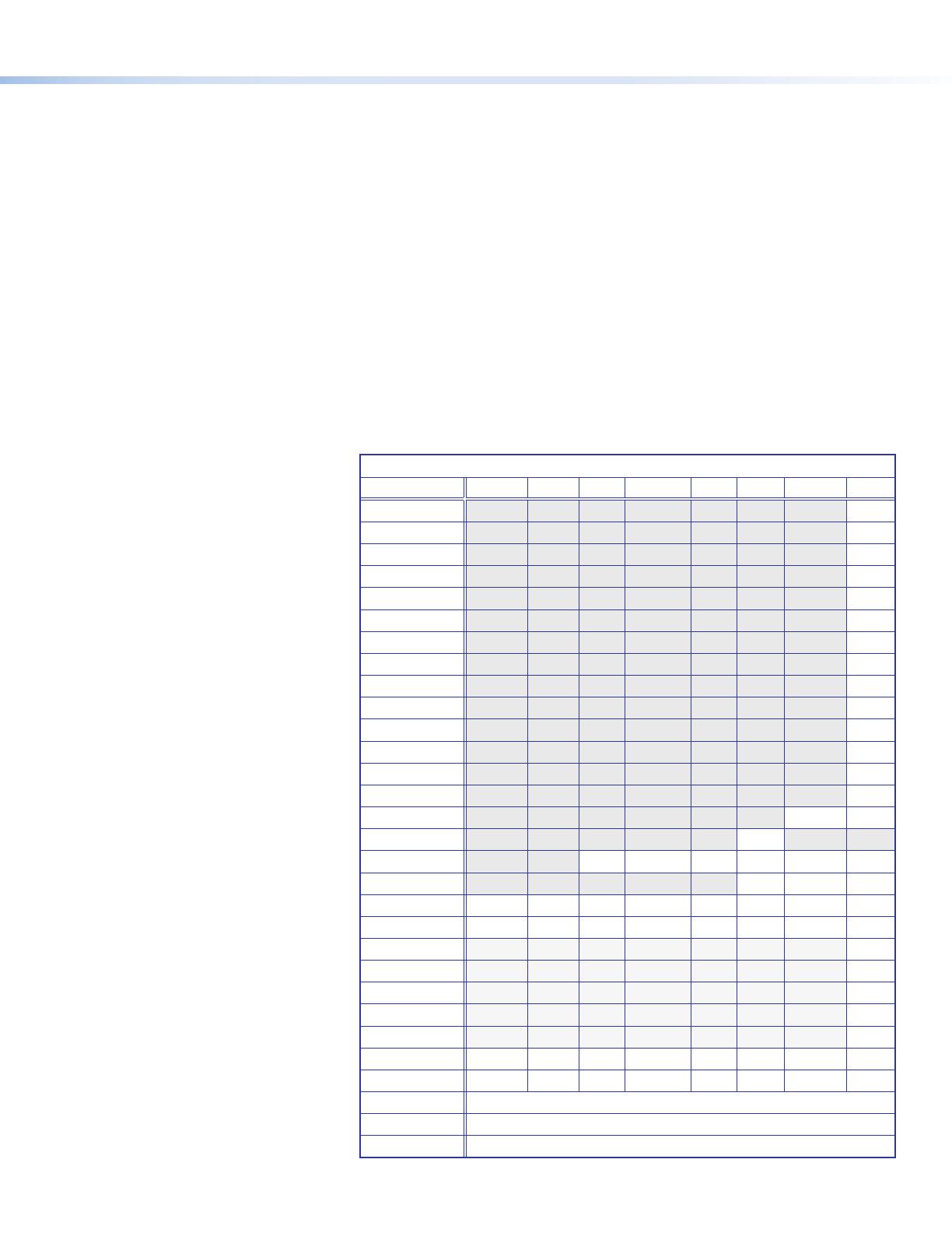
SIS Variables for DSC HD-HD 4K A Resolutions and Rates (
X2!
= 10-76, 201-203)
Resolution 23.98 Hz 24 Hz 25 Hz 29.97 Hz 30 Hz 50 Hz 59.94 Hz 60 Hz
640x480
10
800x600
11
1024x768
12
1280x768
13
1280x800
14
1280x1024
15
1360x768
16
1366x768
17
1440x900
18
1400x1050
19
1600x900
20
1680x1050
21
1600x1200
22
1920x1200
23
480p
24 25
576p
26
720p
29 30 31 32 33 34
1080i
35 36 37
1080p*
38 39 40 41 42 43 44 45*
2048x1080
46 47 48 49 50 51 52 53
2048x1200
54
2048x1536
55
2560x1080
56
2560x1440
57
2560x1600
58
3840x2160
59 60 61 62 63 64** 65** 66**
4096x2160
69 70 71 72 73 74** 75** 76**
Custom Rate 1
201
Custom Rate 2
202
Custom Rate 3
203
*Default output resolution **YUV 4:2:0 limited output format only
3
DSC HD-HD 4K A • Setup Guide (Continued)
Command
ASCII Command
(Host to Scaler)
Response
(Scaler to Host)
Additional Description
Audio Input Format
Set audio input format
E
I1*
X5*
AFMT
}
Afmt I1*
X5*
]
Set the audio input format to
X5*
.
View audio input format
E
I1 AFMT
} X5*
]
View the current audio input format.
Audio Input Gain (Affects analog audio input on 5-pole captive screw connector only.)
Set audio gain
X5$
G Aud
X5$
]
Set the gain on the analog audio input to
X5$
.
Increment gain
+G
Aud
X5$
]
Increase the audio gain by 1 dB to
X5$
.
Decrement gain
-G
Aud
X5$
]
Decrease the audio gain by 1 dB to
X5$
.
View gain
G
X5$
]
View the audio gain level of the current input.
Volume (Analog and embedded digital audio outputs)
Set volume
X5)
V Vol
X5)
]
Set the output volume level to
X5)
.
Increment volume
+V
Vol
X5)
]
Increase the output volume by 1 dB to
X5)
.
Decrement volume
-V
Vol
X5)
]
Decrease the output volume by 1 dB to
X5)
.
View
V
X5)
]
View current volume setting
X5)
.
Output Resolution and Rate
Set output scaler rate
E
1*
X2!
RATE
}
Rate 1*
X2!
]
Select output resolution and refresh rate
X2!
(for
X2!
values, see the output resolution and refresh rate table
on the previous page).
View output rate
E
1 RATE
} X2!
]
Show the current output rate for the DSC.
HDMI Output Format
Set output format
E
1*
X4*
VTPO
}
Vtpo 1*
X4*
]
Select format
X4*
for the HDMI output.
View output format
E
1 VTPO
} X4*
]
Show the current output format (
X4*
) for the DSC.
Screen Saver Mode (Takes effect when no signal is detected on the input.)
Set screen saver mode
E
M1*
X4)
SSAV
}
Ssav M1*
X4)
]
Set the screen saver mode to
X4)
.
View screen saver mode
E
M1 SSAV
} X4)]
View current screen saver mode
X4)
.
Set screen saver duration before
output sync timeout
E
T1*
X2*
SSAV
}
Ssav T1*
X2*
]
Set the period before sync timeout to
X2*
seconds.
View sync timeout duration
E
T1 SSAV
} X2*]
View the amount of time
X2*
before sync timeout.
View screen saver status
E
S1 SSAV
} X6#
]
View the screen saver status
X6#
.
Reset
System reset
E
ZXXX
}
Zpx
]
Reset all device settings to the factory defaults, retaining IP
settings.
4
NOTE:
X2!
= Output scaler rate: See the output resolution and refresh rate table on the previous page for the rate variables.
X2*
= Output sync timeout duration in seconds: 1-500 in 1-second increments. 501 = never (default), 0 = immediate timeout.
X4)
= Screen saver mode: 1 = black (default), 2 = blue, 3 = user screen saver logo.
X4*
= HDMI output format: 0 = Auto (default), 1 = DVI, 2 = HDMI RGB Full, 3 = HDMI RGB Limited, 5 = HDMI YUV 4:4:4 Limited,
7 = HDMI YUV 4:2:2 Limited, 9 = HDMI YUV 4:2:0 Limited.
X5)
= Output volume: 0 dB to -100 dB in 1.0 dB steps. (Default is -10 dB.)
X5$
= Audio input gain: -18 dB to +24 dB. (Default is +12 dB.)
X5*
= Audio input format: 0 = none, 1 = analog, 2 = LPCM-2Ch, 3 = Multi-Ch, 4 = LPCM 2Ch Auto (default), 5 = Multi-Ch Auto.
X6#
= Screen saver status: 0 = active, timer not running, 1 = no active input, timer running, output sync active,
2 = No active input, timer expired, output sync disabled.
68-2803-51 Rev. B
02 18
Basic SIS Commands
The DSC HD-HD 4K A can be configured with specific SIS commands via RS-232, USB, and LAN connection. This table lists
a selection of basic commands. For a full list of SIS commands and variables see the DSC HD-HD 4K A Series User Guide,
available at www.extron.com.
© 2018 Extron Electronics All rights reserved. All trademarks mentioned are the property of their respective owners. www.extron.com
1 / 1

Extron DSC HD-HD 4K A User manual

Category
Video converters
Type
User manual
This manual is also suitable for

Ask a question and I''ll find the answer in the document

Finding information in a document is now easier with AI

Ask the document