Page is loading ...

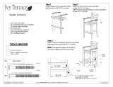
Attach back leg assembly to seat assembly
Step 2
Description
using (4) 3" screws
Model: TD201
Step 1
__(1) Hardware pack
__(1) Back leg assembly
Attach arms to back leg assembly
Qty.
TOOLS NEEDED
and foot rest with (8) 3" screws
__(2) Front leg with arm (LH/RH)
Attach legs to the seat assembly
__(1) Foot rest
__(2) Brace (LH/RH)
ALL HARDWARE IS COATED STAINLESS STEEL
using (2) 2½" screws
__(1) Seat assembly
Step 3
Attach braces between the front and back
legs with the remaining (4) 3" screws.
Note: Compound angle cut on brace
should be attached to the back leg
B
B
RH
LH
B
9/17/2012
ASSEMBLY INSTRUCTIONS
B
B
B
B
16
B - .27 X 3" SOCKET WAFER "A"
2
A - .27 X 2-1/2 SOCKET WAFER "A"
A
A
B
B
4MM T-HANDLE HEX KEY
(INCLUDED)
COMPOUND ANGLE, LONG
EDGE ON THE BOTTOM

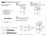
Step 2
Set table upright and tighten all bolts
__(1) Hardware pack
RT348, RCT348, RRT348, RBT348
Models: RT248, RCT248, RRT248, RBT248
Attach the leg assemblies to the table top using
(8) 3" screws.
(4) 3 1/4" Chair bolts.
Step 1
Attach feet to legs using
(4) 3" screws.
Qty. Description
Lay the table top on a flat surface.
4mm HEX KEY: INCLUDED
TOOLS NEEDED
Attach leg braces using
Step 3
__(1) Table top
__(4) Leg
__(2) Foot
__(2) Brace
HARDWARE IS COATED STAINLESS STEEL UNLESS OTHERWISE SPECIFIED
9/19/2012
ASSEMBLY INSTRUCTIONS
4
FINE THREAD
B - 1/4-20 X 3-1/4 WAFER SHCS
Removable table plug
included in table
B
12
A - 14 X 3 SOCKET WAFER "B"
/