Page is loading ...

Model TZ45
Z-Wave Thermostat
INSTALLATION
AND
OPERATION MANUAL
DCN: 141-01773-02
1/19/11
RCS

DCN: 141-01773-02 1/19/11
2
Model: TZ45
Z-Wave Thermostat
This manual applies to the following product revisions or later revisions up to the next manual revision
release:
Product Part No: Firmware Revision
Z-Wave Thermostat 001-01773 1.00.3
Document Revision History
Revision Date Changes
01 10/20/10 Original release
02 1/19/11 Canadian Certification addition
Product Specifications
Product Model: TZ45
Product: Thermostat for Heating and Cooling HVAC System control.
Z-Wave RF communications enabled
Thermostat
Size: 5.7” wide x 4.0” height x 1.2” depth
Display: Graphical LCD, 2.75” x 1.5”, 64x128 pixel
Backlight: Yes, Blue/white, Controllable, on, off, timeout
Contrast: Adjustable on screen
Buttons: 6
LEDs: 4 (3 green, 1 red)
Power: 24VAC from HVAC System
Temperature Sensing Range: -40F to +190F
HVAC System Type Compatible: Standard (gas/electric) or Heat Pump
Multistage System Compatible:
Standard HVAC Systems: 2 stage heating, 2 stage cooling
Heat Pump Systems: 3 stage heating (2 compressor, 1 aux heat), 2 stage cooling
Heat Pump change over valve: Selectable change over with cool or with heat
Remote Sensors: 2 connections, two wire, remote primary or averaging
Communications: Z-Wave RF

DCN: 141-01773-02 1/19/11
3
Table of Contents
Overview ...................................................................................................................................................... 4
Z-Wave® Installation ................................................................................................................................... 5
Setback Mode Operation ........................................................................................................................... 5
Inclusion and Exclusion ............................................................................................................................. 5
Thermostat Control Screen ........................................................................................................................ 6
Temperature Display ................................................................................................................................. 6
Setpoint Display ......................................................................................................................................... 6
Thermostat Operation Buttons................................................................................................................... 7
Setpoint Up/Down Buttons ......................................................................................................................... 7
Clock Display ............................................................................................................................................. 7
LED Displays ............................................................................................................................................. 7
Setting Heating or Cooling Setpoints ......................................................................................................... 8
Schedules Screen .................................................................................................................................... 13
User Settings Screen ............................................................................................................................... 16
Thermostat Info Screen ........................................................................................................................... 22
Main Menu > Installer Settings (Hidden Screen) ................................................................................. 23
Installer Settings Summary ...................................................................................................................... 26
HVAC System Connection ........................................................................................................................ 27
HVAC System Compatibility .................................................................................................................... 27
Remote Communications ........................................................................................................................ 27
HVAC System Operation and Setup ........................................................................................................ 28
Standard HVAC System Types ............................................................................................................... 28
Heat Pump HVAC System Types ............................................................................................................ 28
Power ....................................................................................................................................................... 30
Standard Gas/Electric HVAC System Wiring .......................................................................................... 31
Heat Pump HVAC System Wiring............................................................................................................ 32
FCC ............................................................................................................................................................. 33
IC ................................................................................................................................................................. 33

DCN: 141-01773-02 1/19/11
4
Overview
Z-Wave Thermostat
The Z-Wave thermostat provides for typical thermostat control of a central heating and cooling HVAC
system plus has the added feature of Z-Wave communications for remote control.
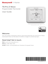
The thermostat has a large, backlit graphical display, control buttons, status LEDs and a temperature
sensor. The thermostat can display multiple screens for different functions of the thermostat. The default
thermostat control screen shown below, will display the current room temperature, heating and cooling
setpoints, system mode, manual-fan mode, time, and status information.
Display operation
Thermostat control screen
Normally the thermostat displays the thermostat control screen as shown above. Using the “Menu”
button, you can access other screens and functions of the thermostat.
Minimized Display Mode
Optionally, you can set the thermostat to show only the temperature in a “minimized” display mode.
This mode can be set on or off in the thermostat “Users Settings” menu.
Backlight
The thermostat has a backlit display for low light and night visibility. It can be set to remain on constantly,
or to turn off after a 20-120 second delay. These are selectable in the User Settings menu.
Status LEDs
The thermostat has four LED’s that displays status information. The LEDs have dynamic “on-screen”
labels that change with the screen being displayed.
Function Control Buttons
The thermostats buttons are “Soft Keys” meaning that they change functions when you change screens.
The function of the button is defined by “on-screen labels” that are dynamic and change when you change
screens
Status
Indicator
LEDs
Setpoint
Up/Down
Buttons
Function Control Buttons
Heating (H)
And
Cooling (C)
Setpoints
On-screen
dynamic
button labels

DCN: 141-01773-02 1/19/11
5
Z-Wave® Installation
Z-Wave controllers from various manufacturers may support the Z-Wave Thermostat General V2 Device
class used by the RCS Z-WAVE Thermostat. The following procedure will allow the thermostat to be
added to a Z-Wave network.
General Programming Procedure
(for controllers supporting the thermostat device class):
1. Set your primary controller to Include mode, to add the thermostat as a node on your network
(see your controller’s user manual for detailed instructions).
2. In the Thermostat’s Main Menu, scroll down to the ZWave Install item. Select the item.
3. Press the YES button in the ZWave Install screen.
Your controller will indicate the thermostat was successfully added to its network (see your controller’s
user manual for details). Also you can check if the thermostat was successfully added to the network
by checking the ZHID (Home ID) and ZNID (Node ID) located in the Thermostat Info screen.
For other specific tasks such as adding the thermostat to Scenes or Groups, or deleting the
thermostat from an existing network, use the Z-Wave Install procedure.
Note: Before adding the thermostat to a Z-Wave Network, check that it does not already belong to
one by viewing the Home and Zone ID’s located in the Thermostat Info screen. An un-configured
thermostat should show zeros for both the Home and Zone IDs. Consult your controller’s user manual
for details on removing a device from a Z-Wave network.
Setback Mode Operation
If your controller does not support full thermostat device class functions, it may still be able to control the
energy saving AWAY mode of the thermostat through BASIC_SET commands.
Sending the BASIC_SET (Value = 0x00), the thermostat will go into the AWAY mode and use the
predefined AWAY setback setpoints. These setpoints are set in the Main Menu Away Setpoints item.
Sending the BASIC_SET (Value = 0xFF), the thermostat will revert back to the mode it was in (Hold or
Run) before the BASIC_SET (Value = 0x00) command was sent.
Note that when the BASIC_SET commands are sent, the TZ45 will momentarily display the new mode on
the Schedule Mode screen.
Inclusion and Exclusion
Inclusion or exclusion is started by putting the controller into add node or remove node state and
performing the General Programming Procedure outlined above. As part of the process, the thermostat
sends a node information frame at normal power.
Low power inclusion or low power exclusion is not possible.

DCN: 141-01773-02 1/19/11
6
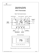
Thermostat Control Screen
Minimized Screen
Main Thermostat Control Screen
The main Thermostat Control Screen is the screen that is normally displayed on the thermostat.
Temperature Display
The thermostat will normally display the current room temperature from the internal temperature sensor
(or a remote sensor, if installed).
Setpoint Display
The current heating and cooling setpoints are displayed next to the Setpoint Up/Down buttons.
74
72
Press any button to return to
the thermostat control screen
The Minimized Screen
shows only the room
temperature.
It is displayed if you set
the “Screen Timeout” in
the User Settings Menu to
a time greater than 0.
If set to 0, the minimized
screen is disabled, and the
main thermostat screen is
normally displayed
MENU
COOL
MODE
72 H
AUTO
FAN HOLD
74
2
75 C
4:30 PM
SYS OFF
ECON
HOLD
NO MSG
Status
Indicator
LEDs
On-screen
dynamic
button labels
Setpoint
Up/Down
Buttons
Heating (H)
And
Cooling (C)
Setpoints
Thermostat Operation Buttons
L1
L2
L3
L4

DCN: 141-01773-02 1/19/11
7
Thermostat Operation Buttons
Menu – go to the Main Menu Screen to select other thermostat settings screens
System Mode – go to the System Mode screen to set thermostat operating mode
Fan Mode – go to the Fan mode screen to set the fan mode
Schedule Mode – go to the Schedule mode screen to set schedule mode or setback
Setpoint Up/Down Buttons
Press either the Up or Down buttons to go to the Heating or Cooling Setpoint screen.
Clock Display
The current time is displayed in the upper left corner of the main screen. Set the clock from the User
Settings Menu. The time will blink when the clock has not been set.
LED Displays
The Thermostat Control Screen has the following LEDs and on-screen labels.
LED L1 Green: System Operation mode.
o “SYS OFF” displayed > HVAC system is OFF. LED Off.
o “SYS MOT” displayed > Minimum Off Time (MOT) delay On is active. LED Off.
o “HEAT ON” displayed > HVAC system is heating. LED On.
o “COOL ON” displayed > HVAC system is cooling. LED On.
o “HEAT MRT” displayed > HVAC system is Heating and Minimum Run Time (MRT) delay off is
active. LED On.
o “COOL MRT” displayed > HVAC system is Cooling and Minimum Run Time (MRT) delay off is
active. LED On.
LED L2 Green: System Stage mode
o no display > 1
st
stage heating or cooling. LED OFF.
o “2
nd
Stg” displayed > Stage 2 heating or cooling is active. LED On.
o “Aux Heat” displayed > Stage 3 heating is active. LED On.
LED L3 Green: Schedule mode. Shows state of Schedule Run/Hold Mode.
o “Run” displayed > Setback schedule is running. LED Off.
o “Hold” displayed > Schedule is off, temperature setpoint hold in effect. LED On.
o “Away” displayed > Away setback mode is active. LED On.
LED L4 RED: Alert LED. Used for system alerts
o No display > No alerts. LED Off.
o Alert Text displayed > Specific alert text (Filter, Maint). LED On.

DCN: 141-01773-02 1/19/11
8
Heating/Cooling Setpoint Setting
Setting Heating or Cooling Setpoints
Setpoint Up and Down Buttons
Press either the Up or Down button in the main Thermostat Control Screen to go to the current system
operating mode (Heating or Cooling) Setpoint screen. as shown below.
Heating /Cooling Setpoint Adjustment Screen
The UP and DOWN buttons adjust the setpoint temperature. Pressing the UP button will increment the
setpoint value by one degree and conversely, pressing the Down button will decrement the setpoint one
degree. Pressing and holding a button will cause the setpoint to continuously change until the button is
released.
Setpoint Range: The setpoints can be set from 50°F to 90°F (4°C to 32°C) for heating or 55°F to 99°F
(10°C to 37°C) for cooling.
Setpoint Push: Note that you cannot lower the cooling setpoint below the heating setpoint. The
thermostat will “push” the heating setpoint lower if you try to lower the cooling setpoint below the heating
setpoint. It maintains a 3 degree separation between the heating and cooling setpoint. The same is true
for raising the heating setpoint above the cooling setpoint. Again the thermostat will “push” the cooling
setpoint up to maintain the 3 degree separation.
NOTE: If the system mode is OFF, pressing either the Up or Down buttons will take you to the
System Mode screen. You must first set an operating mode before you can change the setpoints.
To change the Heat Setpoint you must be in Heating mode, to change the Cool Setpoint you must
be in the Cooling mode. If you are in Auto mode, the mode of the last system call will be the
setpoint screen displayed.
Heating and Cooling
setpoint setting buttons.
Adjust setpoint to
desired temperature.
HEATING SETPOINT
72
DONE
Down
Up
Press Done button to select new setpoint
and exit back to main thermostat screen.

DCN: 141-01773-02 1/19/11
9
System Mode
Press the System Mode button to display the System Mode selection screen.
System Mode Screen
Mode Operation
OFF Mode: System is off. No heating or cooling will come on. If system was on, it will turn off.
HEATING Mode: Only heating will occur.
COOLING Mode: Only cooling will occur.
AUTO Mode: Heating or cooling will come on according to the heating and cooling setpoints. The
system will automatically switch between heating and cooling modes as needed to maintain the
setpoints.
Special Heat Pump Mode
EHEAT Mode: An additional system mode, “EHEAT” for Emergency Heat will be displayed if the
HVAC system type is set to Heat Pump. If there is a compressor failure with the Heat Pump system,
setting the mode to EHEAT will allow the supplemental Aux heat to come on first whenever there is a
call for heating. It also disables the compressor output to prevent further damage to the HVAC
system.
Select system mode
with Up or Down
buttons.
.
SYSTEM MODE
OFF
HEATING
COOLING
AUTO
DONE
Down
Up
Press DONE button to select mode and
exit back to main thermostat screen.
MODE
Press MODE button to go to the System Mode screen

DCN: 141-01773-02 1/19/11
10
Fan Mode
FAN Button
The FAN button controls the HVAC system’s MANUAL fan mode. The current manual fan mode is
displayed above the button. Press the FAN button to go to the FAN MODE selection screen shown below.
Fan Mode Screen
Normally the FAN mode is in the Auto mode (the system fan is automatically controlled by HVAC system).
If you want the FAN on manually, select the ON mode. The fan will run continuously until it is turned off by
selecting AUTO mode.
Optional Fan Mode
Fan Cycler. If the Fan Cycler feature is enabled in the Installer Setup, the additional fan mode “Cycle” will
be shown in the Fan Mode menu. This mode cycles the fan on and off continuously for fresh air
ventilation according to the settings in the Installer Setup.
Select Fan mode with
Up or Down buttons.
FAN MODE
AUTO
ON
DONE
Down
Up
Press DONE button to select mode and exit
back to main Thermostat Control Screen.
FAN
Press FAN button to go to the FAN Mode screen.

DCN: 141-01773-02 1/19/11
11
Schedule Operation
Schedule Mode
The Schedule button sets the schedule operation to RUN or HOLD mode. It also allows you to select an
AWAY setback mode. Pressing the Schedule button will take you to the SCHEDULE MODE menu screen
as shown below.
Schedule Mode Screen
Schedule Modes:
RUN Mode. In the run mode, the thermostat schedule is running and setpoints will change according the
times and temperatures in the internal schedule.
HOLD Mode. This holds the current temperature setpoint settings. The schedule operation is disabled.
AWAY Mode. This is an energy saving setback mode. When selected, the AWAY mode setback
temperature setpoint settings are used. It also inhibits schedule operation. AWAY mode setpoints are set
in the Main Menu “Away Setpoints” item.
Select Schedule mode
with Up or Down
buttons.
.
SCHEDULE MODE
HOLD
RUN
AWAY
DONE
Down
Up
Press DONE button to select mode and
exit back to main thermostat screen.
HOLD
Press the Schedule button to go to the
Schedule Mode screen.

DCN: 141-01773-02 1/19/11
12
Main Menu
The Menu button on the main Thermostat Control Screen selects the MAIN MENU screen. The Main
Menu is a list of the primary thermostat setting screens. Selecting these items will take you to additional
submenu screens for specific settings.
Main Menu Selections
Note. Some menu items are optional. They must be enabled in the Installer Settings menu during
the system setup to show up in the Main Menu list.
Schedules. (Optional). This screen is used to view and set the programmable setback schedules of the
thermostat.
User Settings. This screen is used to set the Clock, Filter Service, Maintenance Service, Screen
Timeout, F/C mode, Sensor Calibration and Backlite/Display settings.
Usage Graph. Shows daily heating and cooling run time hours for a week.
Away Setpoints. Sets the energy savings Away setback heating and cooling setpoints.
ZWave Install. Used to install the thermostat into a ZWave network.
Thermostat Info Screen: This screen shows the firmware versions of the Thermostat and the Zwave
interface, ZWave network IDs, and the HVAC system type setup.
Select menu item with
Up or Down buttons.
.
Menu Selection
Schedules
User Settings
Usage Graphs
Away Setpoints
DONE
Down
Up
Press DONE button to exit back to main
thermostat screen.
SELECT
Press SELECT button to go to the submenu screen.

DCN: 141-01773-02 1/19/11
13
Main menu - Schedules
Schedules is an optional menu item. It will only show up in the menu list if “Schedules” is enabled in the
Installer settings for the thermostat. Provides for local schedule control. The Schedules Screen allows
you to review and set the setback schedule for the thermostat. The thermostat has a 4 x 7 schedule.
Four times a day can be selected for changes to the heating and cooling setpoints. Each day of the week
can have a different schedule. Groups of days can be copied with the same schedule. When the
thermostat is set to “Run” mode, the schedule will be executed daily, with the setpoints being changed as
per that days schedule stored in the thermostat. “Hold” mode stops schedule operation and holds the
current setpoints until changed manually or by network commands.
The Schedules Screen gives you the option of setting a custom setback schedule or to load one of two
preset schedules.
Menu Options
• Heat and Cool: You can change the individual day/hour and setpoints for the Heating and
Cooling schedule by selecting this menu item.
• Preset: Comfort: This is a preset schedule with mild setbacks. Select this menu item to load
the Comfort schedule into the thermostat. Confirmation screen will be displayed for Yes/No entry.
• Preset: EnergyMiser: This is a preset schedule with deeper setbacks. Select this menu item to
load the EnergyMiser schedule into the thermostat. Confirmation screen will be displayed for
Yes/No entry.
Schedules Screen
Select menu item with
Up or Down buttons.
Select Schedule
Heat and Cool
Preset: Comfort
Preset: EnergyMiser
DONE
Down
Up
Press DONE button to exit back to main
thermostat screen.
SELECT
Press SELECT button to go to the submenu screen.

DCN: 141-01773-02 1/19/11
14
Main Menu - Schedules - Heat and Cool Schedule Screen
When you select the Heat and Cool Schedule menu item, the “day” schedule programming screen opens
and the schedule for current day will be displayed. Use the scroll buttons to highlight the data to be
modified. Once the data has been highlighted, use the +/- buttons to change the value of the data.
To copy a days schedule to another day or group of days, move the cursor to “C” on the bottom right of
the schedule screen. When you highlight the “c”, the button below will become “Copy”. Press this button
to change to the Copy Schedule Screen.
Schedule Screen
Increase or decrease
the time or temperature
setting with the
Up/Down buttons.
Saturday Schedule
Time Heat Cool
Morn 06:00 A 70 78
Day 08:00 A 62 85
Even 04:00 P 70 78
Night 10:00 P 62 82 C
DONE
Press DONE button to exit back to Main
Menu screen.
NEXT
Press NEXT button to go to the next day (or if Copy
is selected, go to Copy Schedule screen).
+
-
Use the scroll buttons to navigate
forwards or backwards through the
time and temperature settings.

DCN: 141-01773-02 1/19/11
15
Main Menu - Schedules - Heat and Cool - Copy Schedule
The Copy Schedule screen is a sub screen of the Schedule screen. The Copy Schedule screen allows
you to copy a day’s schedule to another day or group of days.
First select the day to be copied in the Schedule screen. Scroll to the “c” at the bottom of the Schedule
screen to highlight it. The “Next” button will change to the “Copy” button. Press the “Copy” button to open
the Copy Schedule screen.
Scroll through the days and select the days you want to copy the schedule to by setting the “N” under
each day to “Y” by using the Yes/No buttons.
After selecting all the days desired, press the “COPY” button.
Exit the Copy Schedule screen with the “DONE” button.
Copy Schedule Screen
Select Yes or No to
days to copy schedule
to using Up/Down
buttons.
Copy Saturday Schedule
Sun Mon Tue Wed Thu Fri
N N N N N N
DONE
Press DONE button to exit back to day
schedule screen.
COPY
Press COPY button to copy the schedule to the
days with Y selected.
Yes
No
Use the scroll buttons to navigate
forwards or backwards through the
days of the week.

DCN: 141-01773-02 1/19/11
16
Main Menu - User Settings
The User Settings screen allows you to set or change various user options of the thermostat such as the
Clock, Filter and Maintenance service timers, Minimized Screen timeout, Fahrenheit/Celsius mode,
Sensor Calibrations, and Display settings.
User Settings Screen
Menu items:
Set Clock: Go to the Clock setting screen.
Filter Service: Go to the Filter Service Screen. Sets/resets the filter timer/alert.
Maint Service: Go to the Maintenance Service Screen. Sets/resets the maintenance timer/alert.
Screen Timeout: Set the display timeout time in seconds. Options are 0 or 15 to 120 (default set to 0
seconds). This is the time before the main thermostat screen reverts to the Minimized Screen
(temperature display only), after the last button press. Minimized Screen feature is disabled by setting this
time to “0”.
F/C Settings: Go to the F/C Settings Screen. Select which temperature display mode you desire,
Fahrenheit (F) or Celsius (C).
Sensor Calibration: Go to the Sensor Calibration Screen. This screen allows you to set the calibration of
the internal and remote temp sensors.
Backlite/Display: Go to the Backlite/Display settings screen. This menu allows you to set the backlight
timeout period and adjust the display contrast.
Select menu item with
Up or Down buttons.
User Settings
Set Clock
Filter Service
Maint Service
Screen Timeout 0
DONE
Down
Up
Press DONE button to exit back to Main
Menu screen.
SELECT
Press SELECT button to go to the submenu screen.

DCN: 141-01773-02 1/19/11
17
Main Menu - User Settings - Set Clock
The Set Clock screen allows you to set the Thermostat’s internal clock.
To set the Time and Date, move the cursor with the navigation arrows until the data you want to change is
highlighted.
Using the + and – buttons to increment or decrement the data to the desired setting.
When finished, press the SET button to return to the Main Menu screen or wait for screen to timeout.
NOTE: If the clock has been reset by an extended power outage, the Clock display on the
thermostat screen will be blinking. Pressing the MENU button will take you directly to this screen
to set the clock.
Set Clock Screen
Increase or decrease
the time or date setting
with the Up/Down
buttons.
Set Clock
Time: 07:09 PM
Date: 03/07/09
Day: Sat
BACK
Press BACK button to exit back to User
Settings screen without setting the time.
SET
Press SET button to set the time and Exit.
+
-
Use the scroll buttons to navigate
forwards or backwards through the
time and date settings.

DCN: 141-01773-02 1/19/11
18
Main Menu - User Settings - Filter Service
The Filter Service screen will show the accumulated Filter Runtime hours as well as the Service Interval
that will be used to trigger a Filter Message. Any type of HVAC operation that causes the HVAC system
fan to run will cause the Filter Runtime value to increase.
When the Runtime hours equals the Service Interval hours, the Red LED will flash along with a “Filter”
message to remind you to replace the filter. Pressing the Menu button will take you to the Filter Service
screen. Once the filter has been replaced, press the Reset button to reset the Filter Runtime value to
zero.
The Service Interval period can be changed using the +/- buttons.
Filter Service Screen
Filter Service
Filter Runtime 120 HRS
Service Interval 300 HRS
DONE
Press DONE button to exit back to User
Settings screen.
RESET
Press RESET to reset the runtime counter and exit.
Use +/- buttons to increase or
decrease the service interval hours.
+
-

DCN: 141-01773-02 1/19/11
19
Main Menu - User Settings - Maint Service
The Maintenance Service screen will show the accumulated Heat and Cool Runtime hours as well as the
Service Interval that will be used to trigger a Maintenance Message. Any HEAT or COOL type of HVAC
operation will cause the respective Runtime values to increase.
When the combined HEAT and COOL Runtime hours equals the Service Interval hours, the Red LED will
flash along with a “Maint” message to remind you your HVAC system may require periodic maintenance.
Pressing the Menu button will take you to the Filter Service screen. The Reset button can be pressed and
the HEAT and COOL Runtime values will be reset to zero.
The Service Interval period can be changed using the +/- buttons.
Maintenance Service Screen
Maintenance Service
Heat Runtime 120 HRS
Cool Runtime 20 HRs
Service Interval 3000 HR
S
DONE
Press DONE button to exit back to User
Settings screen.
RESET
Press RESET to reset the runtime counters.
Use +/- buttons to increase or
decrease the service interval hours.
+
-

DCN: 141-01773-02 1/19/11
20
Main Menu - User Settings - Sensor Calibration
The Sensor Calibration screen allows you to change the temperature calibration of the internal
temperature sensor. You can change the temperature calibration by +/- 7 degrees.
When the Sensor Calibration screen is selected it will show the current temperature calibration (The (75)
in the example screen below) and the current number of degrees of offset being applied (1 deg in the
example). If the sensor’s actual temp is (74) with 0 degrees of offset and you want it to be 75, then press
“+” to add 1 deg and it will show (75).
To change the temperature calibration, use the scroll buttons to select the internal or a remote sensor.
Once selected, use the + and – buttons to change the temperature calibration to the desired setting.
The value shown in the (xx) is the calibrated or offset temperature that you want the sensor to show.
You can refresh the info on this screen by pressing the right hand (blank) button.
When you close this screen, it may take a few seconds for the temperature displayed on the main
thermostat screen to update to the new temperature.
Sensor Calibration Screen
Select menu item with
Up or Down buttons.
Menu Selection
Internal (75) 0
Remote 1 n/a 0
Remote 2 n/a 0
DONE
Down
Up
Press DONE button to exit back to main
thermostat screen.
Press +/- buttons to increase/decrease the
calibration offset.
+
-
/