Page is loading ...

DCN: 141-02071-01 Page 1
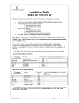
Operation Guide
Model TBZ48
Z-Wave Thermostat
Temperature
Setting
Warmer
Cooler
Fan Mode
Selection
Heating/Cooling
Mode Selection
Battery
Compartment
Room Temperature
Setpoints
Backlite Display
Main Thermostat Screen
72H 80C
72H 80C72H 80C
72H 80C
RUN
74
OFF
AUTO
MODE
FAN

DCN: 141-02071-01 Page 2
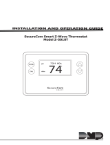
Setting the heating or cooling temperature setpoint
!
To change the Heat Setpoint you must be in the Heating mode, to change the Cool
Setpoint you must be in the Cooling mode. Pressing the Mode button will switch
between the Heat and Cool setpoints.
Setpoint Push: Note that you cannot lower the cooling setpoint below the heating
setpoint. The thermostat will “push” the heating setpoint lower if you try to lower the
cooling setpoint below the heating setpoint. It maintains a 3 degree separation between
the heating and cooling setpoint. The same is true for raising the heating setpoint above
the cooling setpoint. Again the thermostat will “push” the cooling setpoint up to maintain
the 3 degree separation.
Lower
Temperature
Raise
Temperature
Press a button to
go to the setpoint
change screen
Setpoint change screen
Press “DONE” button to set the setpoint and exit back
to the main thermostat screen or wait for the screen to
automatically time out.
Press the up or down arrow buttons to
set the desired temperature setpoint
Pressing the up
or down buttons
will increment the
setpoint 1 degree.
Press and hold
the button to
ramp the setpoint.
72H 80C
72H 80C72H 80C
72H 80C
RUN
74
OFF
AUTO
MODE
FAN
Set to
Set toSet to
Set to
72
Heat
Done
MO
DE
FAN
Setpoint
being
changed

DCN: 141-02071-01 Page 3
Setting the System Mode: Off, Heat, Cool, Auto
System Modes
• Off: System is off. No heating or cooling will come on. If system was on, it will
turn off immediately.
• Heat: Only heating will occur.
• Cool: Only cooling will occur.
• Auto: Heating or cooling will come on according to the heating and cooling
setpoints. The system will automatically switch between heating and cooling
modes as needed to maintain the setpoints.
Special Heat Pump Mode: Emergency Heat
• Heat-E: An additional system mode, “Heat-E” for Emergency Heat will be
displayed if the HVAC system type is set to Heat Pump. If there is a compressor
failure with the Heat Pump system, setting the mode to EHEAT will allow the
supplemental Aux heat to come on first whenever there is a call for heating. It
also disables the compressor output to prevent further damage to the HVAC
system.
Press Mode
button to
change system
mode
72H 80C
72H 80C72H 80C
72H 80C
RUN
74
Off
Auto
MODE
FAN

DCN: 141-02071-01 Page 4
Setting Fan Mode
System Status Indicators
System Operation mode indicator
displayed > System is ON and heating
displayed > System is ON and cooling
blinking > System is ON and heating. Minimum Run Time (MRT) delay off is active.
blinking > System is ON and cooling. Minimum Run Time (MRT) delay off is active.
Staging display
“1” > Stage 1 heating or cooling is ON
“2” > Stage 2 heating or cooling is ON
“3” > Stage 3 heating is ON
For Heat Pump systems only: “Heat-E” > emergency heat mode active
Run/Home/Away display
Run scheduling feature is enabled
Hold scheduling feature is disabled (current setpoints are being used)
Away setback mode is active (setback setpoints are being used)
Notes 1 and 2: See MOT and MRT descriptions on page 9
Press the Fan button to change the Fan mode
• Auto: Fan automatically operated by the HVAC system.
• On: Manual Fan mode. Fan stays on until mode is changed back to Auto.
72H 80C
72H 80C72H 80C
72H 80C
RUN
74
Off
Auto
MODE
FAN

DCN: 141-02071-01 Page 5
Menu Selection
Main Menu Items
• Setup > Basic thermostat settings
• System > Thermostat configuration settings
• Time > Clock time
• Info > Displays thermostat setup info
• ZWave > ZWave installation
Setup Menu Items
Deg F/C Select which temperature display mode, Fahrenheit (F) or Celsius (C).
SensCal Change the temperature calibration by +/- 7 degrees using the + and – buttons
Baklite Sets the time from last button press that the backlite will timeout and turn off. The
Backlite will turn OFF after the selected time expires.
Press and hold Fan
button to go to the main
menu screen
Use the
UP/DOWN
buttons to select
the desired menu
item
Press SELECT to
go to the menu
item screen
Press DONE to go back to
the main thermostat screen
72H 80C
72H 80C72H 80C
72H 80C
RUN
74
Off
Auto
MODE
FAN
SETUP
SETUPSETUP
SETUP
Select
Done
MODE
FAN

DCN: 141-02071-01 Page 6
C Away
Away setpoints are used when the thermostat is set to the setback or away
mode.
H Away
Away setpoints are used when the thermostat is set to the setback or away
mode.
System Menu Items
Systype Select the system type, HP for HeatPump, S for Standard (Gas/Elec)
CO Select the ChangeOver type (HP systems only), changeover with Heat or Cool
Fantype Select Fantype (Gas/Elec only), Gas or Electric
ZWave Install
This menu item allows you to install or uninstall the thermostat into the ZWave network.
Follow the instructions in the ZWave Installation section.
Thermostat Info
The Thermostat Info screen displays the current configuration of the thermostat. This
information is useful for quick check of firmware versions and HVAC system setup. It also
shows the ZWave network settings.
Thermostat information displayed is:
• Version - Firmware version number.
• Node ID – ZWave Node ID
• Home ID –ZWave Home ID
• System Type - Standard or Heat Pump HVAC system
• Fan Type – if HVAC type = Standard: Gas or Elect
OR
• Changeover – if HVAC type = Heat Pump: Changeover with cool or changeover
with heat.

DCN: 141-02071-01 Page 7
Thermostat Operation
Minimum Run Time (MRT)
The thermostat has a Minimum Run Time after the start of any heating or cooling call. This
minimum run time assures even heating and cooling cycles. The MRT delay will keep the
system on even if reaches setpoint or you change the setpoint to a temperature that would
satisfy the call, until the MRT expires. Changing the Mode to OFF will cancel the MRT
and the system will turn off immediately. The MRT can be adjusted in the Installer Settings
menu of the thermostat.
Note: The MRT status is shown in the thermostat System Status on-screen labels.
Minimum Off Time (MOT)
The thermostat has a Minimum Off Time after any heating or cooling call is finished. This
delay prevents rapid heating/cooling cycles and also provides “short cycle protection” for
compressor calls. This delay may be noticeable when you change a setpoint and it does
not respond immediately due to another call that has recently completed and the MOT
delay timer is preventing the system from restarting. The MOT delay time can be adjusted
in the Installer Settings menu of the thermostat. There is a minimum of 5 minutes delay to
assure compressor protection.
Note: The MOT status is shown in the thermostat System Status on-screen labels.

DCN: 141-02071-01 Page 8
Z-Wave® Installation
The TBZ48 is based on the Slave Library in the Z-Wave Ecosystem.
Z-Wave controllers from various manufacturers support the Z-Wave process of adding or
removing a device from a network. The TBZ48 is a Z-Wave Slave and a Z-Wave controller
is required as the primary controller to setup and maintain the network.
The following procedure will allow the TBZ48 to be included or removed from a Z-Wave
network.
NOTE: If the TBZ48 is installed on a network while running on Batteries, it will be
installed as a FLiRs Z-Wave type of device. If the TBZ48 is installed on a network
while powered by the 24VAC, it will be installed as an always listening device and
can act as a router in the Z-Wave ecosystem.
Once installed, do not change how the thermostat is powered.
Inclusion: Including the TBZ48 into an Existing Network
:
1. Set your primary controller to Include mode, to add the TBZ48 as a node on
your network (see your controller’s user manual for detailed instructions).
2. Press the FAN button and hold until the screen changes to the SETUP
screen.
3. Press the UP button until the ZWAVE is shown on the status line, press
Select.
4. INSTALL should be shown on the status line, press Select. The status line
will show the progress as the TBZ48 has been enrolled into a network. Wait
until SUCCESS or FAILED is shown on the status line.
5. Press Done to exit the ZWAVE screen.
6. Press Done again to exit the SETUP screen. The Radio Icon should be
shown indicating the TBZ48 is enrolled into a network.
Your controller will indicate the TBZ48 was successfully added to its network (see
your controller’s user manual for details). Also you can check if the TBZ48 was
successfully added to the network by checking the ZHID (Home ID) and ZNID (Node
ID) located in the INFO screen. Inclusion and exclusion are always done at normal
transmit power mode.
If your controller supports NWI, then you can optionally set the primary to NWI include
mode. Please note that NWI inclusion mode does not end when you have included a
new node. This allows multiple nodes to be included without having to physically go
back to the controller to initiate the next inclusion. Therefore you must manually
terminate NWI inclusion mode at the controller when you have finished including any
new nodes to the network. Since intermediate included nodes will assist the inclusion
process by routing messages, we recommend that nodes close to the primary
controller be installed first, proceeding out in consecutive rings from the controller.
Note: Before adding the TBZ48 to a Z-Wave Network, check that it does not already
belong to one by viewing the Home and Zone ID’s located in the INFO screen. An
un-configured TBZ48 should show a Node ID of 0 and a random Home ID. Consult

DCN: 141-02071-01 Page 9
your controller’s user manual for details on removing a device from a Z-Wave
network.
Exclusion: Removing the TBZ48 from a Network
:
1. Set your primary controller to Remove mode, to remove the TBZ48 as a node
on your network (see your controller’s user manual for detailed instructions).
2. Press the FAN button and hold until the screen changes to the SETUP
screen.
3. Press the UP button until the ZWAVE is shown on the status line, press
Select.
4. REMOVE should be displayed, press Select. The status line will show the
progress as the TBZ48 has been removed from a network. Wait until SUCCESS
or FAILED is shown on the status line.
5. The controller will indicate the TBZ48 has been removed from the network.
The radio icon will disappear from the screen.
Setback Mode Operation
If your controller does not support full thermostat device class functions, it may still be able
to control the energy saving AWAY mode of the thermostat through BASIC_SET
commands.
Sending the BASIC_SET (Value = 0x00), the thermostat will go into the AWAY mode and
use the predefined AWAY setback setpoints. These setpoints are set in the Main Menu
Away Setpoints item.
Sending the BASIC_SET (Value = 0xFF), the thermostat will revert back to the Home
mode it was in before the BASIC_SET (Value = 0x00) command was sent.
Note that when the BASIC_SET commands are sent, the TZ45 will momentarily display the
new mode.

DCN: 141-02071-01 Page 10
FCC/IC
INFORMATION TO USER
This device complies with Part 15 of the FCC Rules. Operation is subject to the following
two conditions: (1) This device may not cause harmful interference, and (2) This device
must accept any interference received, including interference that may cause undesired
operation.
This equipment has been tested and found to comply with the limits for Class B Digital
Device, pursuant to Part 15 of the FCC Rules. These limits are designed to provide
reasonable protection against harmful interference in a residential installation. This
equipment generates and can radiate radio frequency energy and, if not installed and used
in accordance with the instructions, may cause harmful interference to radio
communications. However, there is no guarantee that interference will not occur in a
particular installation. If this equipment does cause harmful interference to radio or
television reception, which can be determined by turning the equipment off and on, the
user is encouraged to try to correct the interference by one or more of the following
measures.
• Reorient or relocate the receiving antenna
• Increase the separation between the equipment and receiver
• Connect the equipment into an outlet on a circuit different from that to which the
receiver is connected
• Consult the dealer or an experienced radio/TV technician for help
Any changes or modifications not expressly approved by the party responsible for
compliance could void the user’s authority to operate the equipment.
This device complies with Industry Canada licence-exempt RSS standard(s). Operation is
subject to the following two conditions: (1) this device may not cause interference, and (2)
this device must accept any interference, including interference that may cause undesired
operation of the device.
Le présent appareil est conforme aux CNR d'Industrie Canada applicables aux appareils
radio exempts de licence. L'exploitation est autorisée aux deux conditions suivantes : (1)
l'appareil ne doit pas produire de brouillage, et (2) l'utilisateur de l'appareil doit accepter
tout brouillage radioélectrique subi, même si le brouillage est susceptible d'en
compromettre le fonctionnement.
/