1
Contents
Product Specifications ............................................2
Operation ..................................................................3
Thermostat Control Screen Function Control
Buttons ....................................................................... 4
Minimized Display Mode .......................................... 5
Menu Map .................................................................6
User Settings ...........................................................7
Set Clock .................................................................... 7
Filter Service ............................................................. 8
Maint Service ............................................................. 9
Screen Timeout ........................................................ 10
F/C Settings ..............................................................11
Sensor Calibration ................................................... 12
Backlite/Display ....................................................... 13
Usage Graph ..........................................................14
ESM Setpoints .......................................................15
ZWave Install ..........................................................16
Inclusion ................................................................... 16
Exclusion .................................................................. 16
Inclusion and Exclusion .......................................... 16
Thermostat Info .....................................................17
Installer Settings ....................................................18
System Settings ....................................................... 19
Thermostat Recovery Operation ............................. 19
Mechanical Settings ................................................ 20
Fan Cycler Settings ................................................. 20
Schedules ...............................................................21
Installation ..............................................................24
Warranty .................................................................25
Index .......................................................................26
Thermostat
Model TZEMT400BB32MAA
User Guide

2
Product Specifications
Specication Description
Product Model: TZEMT400BB32MAA
Product: Thermostat for Heating and Cooling HVAC System control.
Z-Wave™ RF communications enabled
Thermostat
Size: 5.7” wide x 4.0” height x 1.2” depth
Display: Graphical LCD, 2.75” x 1.5”, 64x128-pixel
Backlight: Yes, Blue/white, Controllable, on, off, timeout
Contrast: Adjustable on screen
Buttons: 6
Power: 24VAC from HVAC System
HVAC System Type
Compatible:
Standard (gas/electric) or Heat Pump
Multistage System Compatible: Standard HVAC Systems: 2 stage heating, 2-stage cooling
Heat Pump Systems: 3 stage heating (2-compressor, 1 aux heat), 2-stage cooling
Heat Pump change over valve: Selectable change over with cool or with heat
Communications: Z-Wave™ RF

3
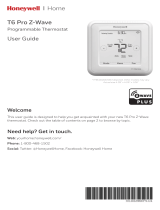
Operation
The model TZEMT400BB32MAA thermostat provides typical thermostat control of a central heating and cool-
ing HVAC system. This thermostat also features a Z-Wave™ module for remote control.
MENU
72
77 H
11:15 PM
Sys O
Run
Filter
AUTO
MODE
AUTO
FAN RUN
74 C
Setpoint
Up/Down Buttons
Temperature
Setpoint Display
Function Control Buttons
Dynamic Labels
Clock Display
Te mperature
Ambient
Display
Normally, the thermostat displays the thermostat control screen as shown above.
Item Description Notes
Clock Display The current time is displayed in the upper
left corner of the main screen. The time will
blink when the clock has not been set.
See "User Settings", Set Clock for
instructions to set time, date, and day.
Function Control Buttons
and Dynamic Labels
As you press the function buttons and
navigate through menus, the button labels
will change. Dynamic button labels are
displayed above or beside each button.
Setpoint Display and
Setpoint Up/Down
Buttons
The current heat and cool temperature
setpoints are displayed. These setpoints
may be set using the Z-Wave control
system, by pressing the Setpoint Up/
Down buttons, or through the thermostat’s
internal schedule
Note: If the system mode is set to HEAT
the setpoint Up/Down buttons change the
heat setpoint. If the system mode is set
to COOL the setpoint Up/Down buttons
change the cool setpoint. In AUTO mode,
the buttons change the heating or cooling
setpoint of the last active mode.
The setpoints will push each other if they
are adjusted to within the minimum heat/
cool separation setting. This is normally 3
degrees.
The internal schedule is disabled by
default. See system setting H/C Delta for
more information.
Temperature Display The thermostat displays the ambient
temperature as sensed by the internal
temperature sensor.
The internal temperature sensor can be
calibrated. See the Sensor Calibration
section.

4
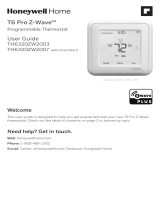
Thermostat Function Control Buttons
MENU
72
77 H
11:15 PM
Sys O
Run
Filter
AUTO
MODE
AUTO
FAN RUN
74 C
System
Mode Button
Fan Mode
Button
Schedule
Mode Button
Menu Button
Button Description
Menu Other thermostat menus can be accessed by pressing the MENU button.
System Mode Used to change the system mode
Off: System off
Heating: Heating only on
Cooling: Cooling only on
Auto: Heating/Cooling on as necessary
Fan Mode Used to change the fan mode
Auto: Fan on when cooling/heating is necessary
On: Fan constantly on
Schedule Mode Used to change the schedule mode
Hold: System maintains the current temperature setpoints. Schedules are disregarded.
Run: Run the system schedule (or Z-Wave controlled schedule)
Energy Saving Mode: Temperature setpoints in ESM Setpoints are maintained. See
ESM Setpoints for more information.

5
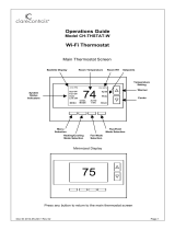
Minimized Display Mode
Optionally, you can set the thermostat to show only the temperature in minimized display mode. This mode can
be enabled or disabled in the Users Settings screen.
Î See Screen Timeout on page for more information.
72

6
Menu Map
The menus are accessed by pressing the MENU button on the main screen.
A. "User Settings"
1. Set Clock
2. Filter Service
3. Maint. Service
4. Screen Timeout
5. F/C Settings
6. Sensor Callibration
7. Backlite/Display
B. "Usage Graph"
C. "ESM Setpoints"
D. "ZWave Install"
E. "Thermostat Info"
F. "Installer Settings" (hidden)
1. Display Lock
2. System Settings
a. Mechanical Settings
1. Type
2. Fan Type
3. C/O Type
4. 2nd Stage Heat
5. Aux Heat
6. 2nd Stage Cool
b. Sched Enable
c. Recovery Enable
d. H/C Delta
e. H Delta Stg1 ON
f. H Delta Stg1 OFF
g. H Delta Stg2 ON
h. H Delta Stg2 OFF
i. H Delta Stg3 ON
j. H Delta Stg3 OFF
k. C Delta Stg1 ON
l. C Delta Stg1 OFF
m. C Delta Stg2 ON
n. C Delta Stg2 OFF
3. Fan Cycler
4. Min Cool SP
5. Min Run Time
6. Min Off Time
7. T-Sense Match
8. Fan Cycler
a. Fan ON Time
b. Fan OFF Time
9. Restore Defaults
G. "Schedules" (disabled by default)
1. Heat and Cool
2. Preset: Comfort
3. Preset: EnergyStar
4. Copy (small c on each schedule screen)

7
User Settings
A.1 Set Clock
The Set Clock screen allows you to set the thermostat’s internal clock.
Î If the clock has been reset by an extended power outage, press the MENU button, scroll to the User Settings button and
select, select the Set Clock screen and set clock.
Set Clock
Back Set
Time 11 : 15 AM
Date 01 / 01 / 09
Day Thu
+
-
Set the Clock
1. Press the MENU button.
2. Scroll to User Settings and press the Select button.
3. Scroll to Set Clock and press the Select button.
4. Scroll to the item you want to change (hour, minute, day part, month, day, year, day of week).
5. Press the plus (+) or minus (-) buttons to adjust the item.
6. Press the Set button to save the changes.

8
Filter Service
The Filter Service screen will show the accumulated Filter Runtime hours as well as the Service Interval that
will be used to trigger a Filter Message. Any type of HVAC operation that causes the HVAC system fan to run
will cause the Filter Runtime value to increase.
When the Runtime hours equals the Service Interval hours, a “Filter” message will appear to remind you to re-
place the media filter or service the air cleaner. Once the filter has been replaced, press the Reset button to reset
the Filter Runtime value to zero.
Filter Service
Done Reset
Filter Runtime 184 HRS
Service Interval 300 HRS
+-
View/Reset Filter Runtime
1. Press the MENU button.
2. Scroll to User Settings and press the Select button.
3. Scroll to Filter Service and press the Select button. The Filter Runtime is displayed in hours.
4. To reset the Filter Runtime counter, press the Reset button.
Î The Filter Runtime counter should be reset each time the lter is changed.
Change the Filter Service Interval
1. Press the MENU button.
2. Scroll to User Settings and press the Select button.
3. Scroll to Filter Service and press the Select button.
4. Press the plus (+) or minus (-) buttons to adjust the service interval.
Î The service interval can be set between 100 and 4000 hours in 100 hour increments. Factory default is 300 hours.
Disable the Filter Service Interval
When the filter service interval is disabled, the runtime counter will continue to count the runtime, but the filter
service indicator will never be displayed.
1. Press the MENU button.
2. Scroll to User Settings and press the Select button.
3. Scroll to Filter Service and press the Select button.
4. Press the minus (-) button until Disabled is displayed

9
Maint Service
The Maintenance Service screen shows the accumulated Heat and Cool Runtime hours as well as the Service
Interval that will be used to trigger a Maintenance Message. Any HEAT or COOL type of HVAC operation will
cause the respective Runtime values to increase.
When the combined HEAT and COOL Runtime hours equals the Service Interval hours, a “Maint” message will
appear to remind you your HVAC system may require periodic maintenance. Press the Menu button to enter the
Maintenance Service screen. The Reset button can be pressed and the HEAT and COOL Runtime values will be
reset to zero.
Maintenance Service
Done Reset
Heat Runtime 200 HRS
Cool Runtime 300 HRS
Service Interval 3000 HRS
+-
Change the Maintenance Service Interval
1. Press the MENU button.
2. Scroll to User Settings and press the Select button.
3. Scroll to Maint Service and press the Select button.
4. Press the plus (+) or minus (-) buttons to adjust the service interval.
Î The service interval can be set between 200 and 4000 hours in 100 hour increments.
Disable the Maintenance Service Interval
When the maintenance service interval is disabled, the runtime counter will continue to count the runtime, but
the maintenance service indicator will never be displayed.
1. Press the MENU button.
2. Scroll to User Settings and press the Select button.
3. Scroll to Maint Service and press the Select button.
4. Press the minus (-) button until Disabled is displayed

10
Screen Timeout
This is the time before any screen reverts to the Minimized Screen (temperature display only), after you stop
pushing buttons. Minimized Screen feature is disabled by setting this time to “0”.
User Settings
Set Clock
Filter Service
Maint Service
Screen Timeout 0
Done Select
Change the Screen Timeout
1. Press the MENU button.
2. Scroll to User Settings and press the Select button.
3. Scroll to Screen Timeout
4. Press the plus (+) or minus (-) buttons to adjust the time (in seconds).
Î The screen time-out can be set between 0 and 120 seconds. Zero (0) is the default setting. When set to Zero (0), the
minimized screen feature is disabled.
Disable the Minimized Display
1. Press the MENU button.
2. Scroll to User Settings and press the Select button.
3. Scroll to Screen Timeout
4. Press the minus (-) button until zero (0) is displayed.

11
F/C Settings
The F/C Settings screen is use to select the temperature display mode. Fahrenheit (F) or Celsius (C) are the two
available modes.
F/C Settings
F/C Mode F
Done +-
Change the Temperature Mode
1. Press the MENU button.
2. Scroll to User Settings and press the Select button.
3. Scroll to F/C Settings and press the Select button.
4. Press the plus (+) or minus (-) buttons to change the temperature mode. Select F for Fahrenheit or C for Celsius.

12
Sensor Calibration
The Sensor Calibration screen is used to change the temperature calibration of the internal temperature sensor.
The temperature calibration can be changed by +/- 7 degrees.
When the Sensor Calibration screen is selected, the current temperature calibration is displayed. In the example
screen, the calibrated temperature is 77 and the number of degrees of offset being applied is 1.
Sensor Calibration
Internal (77) 1
Done +-
Change the Sensor Calibration
1. Press the MENU button.
2. Scroll to User Settings and press the Select button.
3. Scroll to Sensor Calibration and press the Select button.
4. Press the plus (+) or minus (-) buttons to change the sensor calibration.
Î After this screen is closed, it may take a few seconds for the temperature displayed on the main thermostat screen to
update to the new temperature.

13
Backlite/Display
The Backlite/Display screen is used to set the backlight time-out and contrast.
Backlite Timeout is the time (in seconds) from the last button press to the backlight going out. The time-out can
be set between zero (0) and one hundred and twenty (120) seconds. Thirty (30) is the default setting. When set
to zero (0), the backlight will remain always on.
Contrast sets the contrast level of the LCD display. The contrast can be set between zero (0) and twenty (20).
Ten (10) is the default setting. If the display is too light, using a higher number. If dark lines appear in the dis-
play, use a lower number.
Backlite/Display
Backlite Timeout 60
Contrast 10
Done +-
Adjust the Backlight
1. Press the MENU button.
2. Scroll to User Settings and press the Select button.
3. Scroll to Backlite/Display and press the Select button.
4. Scroll to Backlite Timeout.
5. Press the plus (+) or minus (-) buttons to change the number of seconds.
Î The backlight time-out can be set between 0 and 120 seconds. Thirty (30) is the default setting. When set to Zero
(0), the backlight will remain always on.
Adjust the Contrast
1. Press the MENU button.
2. Scroll to User Settings and press the Select button.
3. Scroll to Backlite/Display and press the Select button.
4. Scroll to Contrast.
5. Press the plus (+) or minus (-) buttons to change the contrast value.
Î The contrast can be set between 0 and 20. Ten (10) is the default setting.

14
Usage Graph
The Usage Graph shows daily heating and cooling runtime hours for a week.
Heating time (Hrs)
Done Cool
20
15
10
5
Sun Mon TueWed ThuFri Sat
The button in the lower right corner will change depending on what is being displayed. When the heating time
is displayed, the button will read Cool. When the cooling time is displayed, the button will read Heat. Press the
Heat/Cool button to display the heating/cooling time.

15
ESM Setpoints
Energy Saving Mode (ESM) Setpoints are the setpoints used when the Energy Saving Mode schedule is select-
ed in the Schedule Mode screen.
Energy Saving Mode Setpoings
ESM - Heat 65
ESM - Cool 80
Done +-
Adjust ESM Setpoints
1. Press the MENU button.
2. Scroll to ESM Setpoints and press the Select button.
3. To adjust the heat setpoint, scroll to ESM - Heat. Press the plus (+) or minus (-) buttons to adjust the setpoint.
4. To adjust the cool setpoint, scroll to ESM - Cool. Press the plus (+) or minus (-) buttons to adjust the setpoint.

16
ZWave Install
Z-Wave™ controllers from various manufacturers may support the Z-Wave™ Thermostat General V2 Device
class used by the Trane Z-Wave™ Thermostat. The following procedure will allow the thermostat to be added to
a Z-Wave™ network.
Î If you are using a controller that is not a Schlage bridge, consult the instructions that came with the controller to nd out
how to enroll a new device.
Inclusion
1. Install a new, high-quality 9-volt battery into the bridge.
2. Hold the bridge within 6 feet (1.8 meters) of the thermostat throughout the entire inclusion process.
Î After you begin the inclusion process, you have 30 seconds to complete the remainder of the steps. Study the steps
below before beginning.
3. Press and release the plus (+) button on the bridge.
4. Press the MENU button on the thermostat.
5. Scroll to ZWave Install. Then press the Select button.
6. Press the Yes button.
7. Observe the lights on the bridge. The orange light will blink while enrollment is taking place. Enrollment is complete when
the orange light becomes solid.
Exclusion
1. Install a new, high-quality 9-volt battery into the bridge.
2. Hold the bridge within 6 feet (1.8 meters) of the thermostat throughout the entire exclusion process.
Î Note: After you begin the enrollment process, you have 30 seconds to complete the remainder of the steps. Study the
steps below before beginning.
3. Press and release the minus (-) button on the bridge.
4. Press the MENU button on the thermostat.
5. Scroll down to Z-Wave Install and press the Select button.
6. Press the Yes button to exclude the thermostat.
7. Observe the lights on the bridge. The orange light will blink while exclusion is taking place. Exclusion is complete when the
orange light becomes solid.
Inclusion and Exclusion with Other Controllers
Inclusion or exclusion is started by putting the controller into add node or remove node state and performing
the procedure outlined above. As part of the process, the thermostat sends a node information frame at normal
power. Low power inclusion or low power exclusion is not possible.

17
Item Description
TZEMT400BB32 Model Number
Ver: 01.00.10 Firmware version
Î This number may vary.
ZVER: 02.00.9 Z-Wave version
Î This number may vary.
ZNID: 004 Z-Wave node ID
Î This number may vary.
ZHID: 01.07.37.bd Z-Wave Home ID
Î This number may vary.
System Type: Standard System type may be Standard or Heatpump
Fan Type: Gas Fan type may be Gas or Elect (electric)
Thermostat Info
Done
TZEMT400BB32 Ver: 01.00.10
ZVER: 02.00.9 ZNID: 004
ZHID: 01.07.37.bd
System Type: Standard
Fan Type: Gas
Thermostat Info
The Thermostat Info screen displays information about the thermostat and the system the thermostat controls.
This information will be helpful if you need to contact customer support.
Thermostat Info
Done
TZEMT400BB32 Ver: 01.00.10
ZVER: 02.00.9 ZNID: 004
ZHID: 01.07.37.bd
System Type: Standard
Fan Type: Gas

18
Installer Settings
Î The Installer Settings screen is a hidden screen designed for installer use only. Do not change any settings in this
screen unless you are a qualied service technician.
Installer Settings
Display Lock N
System Settings
Max Heat SP 90
Min Cool SP 60
Done +-
Î Changing these settings will affect the operation of the heating/cooling system.
To view and edit these settings:
1. Press the MENU button.
2. Press and hold the two middle buttons simultaneously until the Installer Settings menu is displayed.
3. Scroll to the setting you want to change. Press the plus (+) or minus (-) button to adjust the setting.
4. Press the Done button when you are nished.
Setting Range Default Description
Display Lock Y or N N Locks or unlocks the thermostat buttons. When the buttons are
locked, the main menu can still be accessed, but no menu options
may be selected. The Installer Settings hidden button operation is
always operational, allowing Display Lock to be turned off.
Max Heat SP 55F to 90F
(12C-32C)
90F (32C) Sets the maximum heating setpoint value. Will not ramp or accept
setpoints higher than this maximum.
Min Cool SP 60F to 99F
(15C-37C)
60F (15C) Sets the minimum cooling setpoint value. Will not ramp or accept
setpoints lower than this minimum.
Minimum Run
Time (MRT)
1- 9 Minutes 3
Sets the minimum run time before a heating/cooling cycle can turn
off to prevent rapid cycling. Thermostat screen will display Cool ON
or Heat ON while the minimum run time is being enforced.
Minimum Off
Time (MOT)
5-9 Minutes 5 Sets the minimum off time before another heating/cooling cycle
can begin to provide compressor short cycle protection. Thermostat
screen will display WAIT when minimum off time is being enforced.
T-Sense
Match
1-6 2 Sample rate of temperature sensor
Low Sample Rate = Less sensitive (slower response)
High Sample Rate = More sensitive (faster response)
Restore
Defaults
n/a n/a Sets all of the thermostat settings back to the factory defaults.

19
System Settings
Î Changing these settings will affect the operation of the heating/cooling system.
To view and edit these settings:
1. Press the MENU button.
2. Press and hold the two middle buttons simultaneously until the Installer Settings menu is displayed.
3. Scroll to System Settings and press the Select button.
4. Scroll to the setting you want to change. Press the plus (+) or minus (-) button to adjust the setting.
5. Press the Done button when you are nished.
Î Note on Delta Settings: The Delta T Setting is the delta, or difference between, the setpoint and current temp for
determining when a heat or cool call comes on. The “delta” is the number of degrees away from setpoint.
Setting Range Default Description
Schedule
Enable
Y or N N When enabled, the local thermostats scheduler function is enabled.
Recovery
Enable
Y or N N See Thermostat Recovery Operation below.
H/C Delta 3 - 15
degrees
3 Sets the minimum separation between heating and cooling
setpoints. Attempts to lower the cooling below the heating setpoint
by this amount will PUSH the heating setpoint down to maintain
this separation. Same for setting the heating setpoint above the
cooling setpoint, it will PUSH the cooling setpoint up to maintain this
separation.
Heating Delta
Stage 1 ON
1 to 8
degrees
1 Sets the delta from setpoint that stage 1 heating starts.
Heating Delta
Stage 1 OFF
0 to 8
degrees
0 Sets the delta from setpoint that stage 1 heating stops. Stage 1
turns off at setpoint minus (-) Delta Stage 1.
Heating Delta
Stage 2 ON
1 to 8
degrees
2 Sets the delta from setpoint that stage 2 heating starts.
Heating Delta
Stage 2 OFF
0 to 8
degrees
0 Sets the delta from setpoint that stage 2 heating stops. Stage 2
turns off at setpoint minus (-) Delta Stage 2.
Heating Delta
Stage 3 ON
1 to 8
degrees
3 Sets the delta from setpoint that stage 3 heating starts.
Heating Delta
Stage 3 OFF
0 to 8
degrees
0 Sets the delta from setpoint that stage 1 heating stops. Stage 3
turns off at setpoint minus (-) Delta Stage 3.
Cooling Delta
Stage 1 ON
1 to 8
degrees
1 Sets the delta from setpoint that stage 1 cooling starts.
Cooling Delta
Stage 1 OFF
0 to 8
degrees
0 Sets the delta from setpoint that stage 1 Cooling stops. Stage 1
turns off at setpoint plus (+) Delta Stage 1.
Cooling Delta
Stage 2 ON
1 to 8
degrees
2 Sets the delta from setpoint that stage 2 cooling starts.
Cooling Delta
Stage 2 OFF
0 to 8
degrees
0 Sets the delta from setpoint that stage 2 Cooling stops. Stage 2
turns off at setpoint plus (+) Delta Stage 2.
Thermostat Recovery Operation
The Recover feature is active only when “Schedule” is enabled and the schedule mode is set to “RUN”
Recovery operation, when enabled, will start the cooling or heating system so that the desired comfort temperature is reached by the
next scheduled set point time. The advance start time calculation is a learned process that is recalculated and adjusted each day until
the room temperature is at the target temperature at the schedule time. When the thermostat is in Recovery mode the display will show
“Recov”.
Recovery works for all scheduled periods (1-4) and in HEAT, COOL or AUTO modes. While in Recovery the Aux-Heat stage will not
engage.
The maximum Recovery time is one hour.

20
Mechanical Settings
Î Changing these settings will affect the operation of the heating/cooling system.
To view and edit these settings:
1. Press the MENU button.
2. Press and hold the two middle buttons simultaneously until the Installer Settings menu is displayed.
3. Scroll to System Settings and press the Select button.
4. Scroll to Mechanical Settings and press the Select button.
5. Scroll to the setting you want to change. Press the plus (+) or minus (-) button to adjust the setting.
6. Press the Done button when you are nished.
Setting Range Default Description
Type Gas/Elec or
Heatpump
Gas/Elec Selects HVAC type, Gas/Electric or Heatpump
Fan Type Gas or Elec Gas Selects the Fan type if system is Gas or Electric
C/O Type w/Cool or w/
Heat
w/Cool Set the Heat pump Changeover type
2nd Stage
Heat
Y or N N Enables the 2nd Stage Heat operation
Aux Heat
(HP)
Y or N Y Enables the Auxiliary Heat operation. Typically the Aux Heat will be
heat-strips in a Heatpump system
2nd Stage
Cool
Y or N N Enables the 2nd Stage Cool operation
Fan Cycler Settings
Î Changing these settings will affect the operation of the heating/cooling system.
To view and edit these settings:
1. Press the MENU button.
2. Press and hold the two middle buttons simultaneously until the Installer Settings menu is displayed.
3. Scroll to Fan Cycler and press the Select button.
4. Scroll to the setting you want to change. Press the plus (+) or minus (-) button to adjust the setting.
5. Press the Done button when you are nished.
Setting Range Default Description
Fan ON Time 0-120
minutes
0 (=OFF)
The fan cycler function cycles the HVAC system fan for an ON
period followed by an Off period continuously. Used to provide
minimum air ventilation requirements. When the Fan ON time is
set to a value greater than 0, an additional Cycler FAN mode is
present when pressing the FAN button.
Fan OFF Time 10-120
minutes
10
Page is loading ...
Page is loading ...
Page is loading ...
Page is loading ...
Page is loading ...
Page is loading ...
Page is loading ...
Page is loading ...
/