Page is loading ...

EEnneerrggyy MMaannaaggeemmeenntt TThheerrmmoossttaatt QQuuiicckk GGuuiiddee —— CCaatt.. ## RRFFTTSSTTAATT0011
Purpose:
This Quick Guide provides the basic instructions for wiring, installing, and
programming the Helios thermostat into a Z-Wave® network. For more
detailed instructions refer to the complete Energy Management
Thermostat Installation and Operation Manual. This is located online at
www.cooperwiringdevices.com/AspireRF.
HVAC System / Thermostat Overview
The RFTSTAT01 connects to the HVAC system’s thermostat connections just
like a traditional thermostat.
HVAC System Compatibility
The RFTSTAT01 is compatible with most heating and cooling systems. There
are two types of HVAC systems:
Standard (gas/electric)
Heat Pump systems
The system type is selectable from the Thermostat Installer Screen by using the Function Control Buttons to access Menu > System Settings
> Mechanical Settings submenu. Refer to the complete Installation and Operation Manual for detailed explanation.
Standard HVAC systems: For Gas heating or Electric heating.
Heat Pump HVAC systems: Supports changeover valve operation for either changeover with cooling or changeover with heating.
Multi-Stage HVAC Compatibility:
For Standard HVAC systems the HVAC outputs support 2 stages of heating and 2 stages of cooling.
For Heat Pump HVAC systems, the HVAC outputs support 3 stages of heating (2 compressor/1 Aux Heat) and 2 stages of cooling.
Remote Communications
The RFSTAT01 is embedded with a Z-Wave module for communicating wirelessesly with Z-Wave compatible control systems.
WIRING / INSTALLATION
The RFTSTAT01 requires 24VAC power from the HVAC system it is controlling. Refer to Figure 1 for connection to a Standard HVAC System
and Figure 2 for a Heat Pump HVAC System.
• Connect the 24V/AC Common (typically the Blue wire/terminal) from the HVAC system to the thermostat terminal block 24Com
• Connect the 24V/AC Return (typically the Red wire/terminal) from the HVAC system to the thermostats HVAC System terminal
block 24RH or 24RC terminals
NOTE – the 24RH and 24RC terminals are default tied together in the thermostat. Most HVAC systems have a common heating and
cooling transformer. If you have a system with separate heating and cooling transformers, you will need to split the RH and RC jumper
by cutting the trace on the PCB. Refer to the complete Thermostat Manual for a detailed explanation.
NOTE – Do NOT split the 24RC/24RH terminals for a Heat Pump system.
RFTSTAT-PT (REV. A)
ENGLISH
I
I
N
N
U
U
.
.
S
S
.
.
A
A
.
.
:
:
C
ooper Wiring Devices, 203 Cooper Circle, Peachtree City, GA 30269 • 866-853-4293
Status
Indicator
LEDs
On-Screen
Dynamic
Button
Labels
Setpoint
Up/Down
Buttons
Heating (H)
and
Cooling (C)
Setpoints
Function Control Buttons
BLUE
RED
WHITE
ORANGE
GREEN
YELLOW
BROWN
C 24V/AC COMMON
R 24V/AC RETURN
W 1 HEAT STAGE 1
W 2 HEAT STAGE 2
G FAN
Y1 COMPRESSOR STAGE 1
Y2 COMPRESSOR STAGE 2
THERMOSTAT CONNECTION
24RH
W1 HEAT
W2/O
G FAN
Y1 COMP
Y2 COMP
24COM
24RC
RFTSTAT01
JP1: Internal RC/RH Jumper
See notes
Typical HVAC system
thermostat wiring color codes
Be sure to verify your systems
wiring color codes
Standard HVAC System
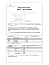
FIG. 1: STANDARD GAS/ELECTRIC HVAC SYSTEM WIRING
BLUE
RED
WHITE
ORANGE
GREEN
YELLOW
BROWN
C 24V/AC COMMON
R 24V/AC RETURN
W 1 AUX HEAT
CHANGE OVER VALUE O or B
G FAN
Y1 COMPRESSOR STAGE 1
Y2 COMPRESSOR STAGE 2
THERMOSTAT CONNECTION
24RH
W1 HEAT
W2/O or B
G FAN
Y1 COMP
Y2 COMP
24COM
2
4RC
RFTSTAT01
JP1: Internal RC/RH Jumper
See notes
Typical HVAC system
thermostat wiring color codes
Be sure to verify your systems
wiring color codes
H
eat Pump HVAC System
FIG. 2: HEAT PUMP HVAC SYSTEM WIRING
Figure 1:
Installation Notes – Standard HVAC System Setup
System Type: Set the system type to Gas/Elect in the Mechanical
Settings menu of the Installer Setup. This is the default setting.
Single Stage systems use W1 for heating stage 1 and Y1 for cooling
stage 1.
Two Stage Heating systems use W1 for stage 1 heating and W2 for
stage 2 heating.
Two Stage Cooling systems use Y1 for stage 1 cooling and Y2 for
stage 2 cooling.
HVAC system transformer: If you have an integrated heating and
cooling system with a single transformer, do NOT cut jumper JP1.
This is typical of most central HVAC systems.
Figure 2 :
Installation Notes – Heat Pump HVAC System Setup
System Type: Set the system type to Heat Pump in the Mechanical
Settings menu of the Installer Setup.
Single Stage Compressor Systems: Use Y1 for stage 1 heating/
cooling, and W1 for stage 2 Aux Heating.
Two Stage Compressor Systems: Use Y1 for stage 1 heating/cooling
and Y2 for stage 2 heating/cooling and W1 for stage 3 Aux
Heating.
Change Over Valve: You must configure the thermostat’s
changeover valve setting to work correctly with your HVAC system.
Check your HVAC system documentation to be sure.
• Changeover settings are made in the Installer Settings > System
Settings > Mechanical Settings menu.
• Changeover with “Cool” is the default setting and typical for
most systems.
• If you get cooling when you expect heating, change the C/O
type to the opposite setting.

Z-Wave INSTALLATION
Aspire RF’s controllers (RFHDCSG and RFTDCSG) support the Helios Z-wave Thermostat General Version 2 Device class. The following
procedure will allow the thermostat to be added to a Z-Wave network.
1. Set your primary controller to Install mode to add the thermostat as a node on your network (Refer to the Aspire RF User Guide for more
detailed instructions).
2. In the Thermostat’s Main Menu, scroll down to the Z-Wave Install item. Select the item.
3. Press the YES button in the Z-Wave Install screen.
4. The controller will indicate that the thermostat was successfully added to the RF network.
5. For deleting the thermostat from an existing network set the Primary Controller to Uninstall mode.
6. In the Thermostat’s main menu, scroll down to the Z-Wave Install item. Select this item. Press the YES button in the Z-Wave Install screen.
NOTE: Before adding the RFTSTAT01 to a Z-Wave Network, check that it does not already belong to one by viewing the Home and Zone
ID’s located in the Thermostat Info screen. An un-configured thermostat should show zeros for both the Home and Zone IDs. O
Z-Wave APPLICATIONS
After the RFTSTAT01 has been installed in the Z-Wave network, you now have the ability to:
• Control the thermostat temperature from the Aspire RF controller
• Control the HVAC mode from the Aspire RF controller
• Add a specific thermostat setting or mode to a customized scene. This scene can be activated from a Aspire RF controller.
NOTE: thermostat control is not included in scenes that are loaded into the Wallmount Scene Controller (RFWDC)
• Ability to easily set thermostat schedules with the Aspire RF controller.
NOTE – By using Aspire RF’s HS2-Pro software (RFBER and RFUSB-PRO), you can have the ability to remotely control your thermostat setting
through an Internet connection.
LED DISPLAYS
The Thermostat Control Screen has the following LEDs and on-screen labels.
LED L1 Green: System Operation mode.
•
HVAC system is OFF – “SYS OFF” is displayed. LED OFF
• Minimum Off Time (MOT) delay On is active- “SYS MOT” is displayed LED OFF
• HVAC system is heating – “HEAT ON” is displayed LED ON
• HVAC system is cooling – “COOL ON” is displayed LED ON
•
HVAC system is Heating and Min Run Time (MRT) delay off is active.
“HEAT MRT” is displayed. LED ON
•
HVAC system is Cooling and Min Run Time (MRT) delay off is active.
“COOL MRT” is displayed LED ON
L
ED L2 Green: System Stage mode
• 1st stage heating or cooling not active – No display. LED OFF
• 2nd stage heating or cooling is active – “2nd Stg” displayed. LED ON
• Stage 3 heating is active – “Aux Heat” is displayed. LED ON
LED L3 Green: Schedule mode.
• Setback schedule is running – “Run” is displayed. LED OFF
• Schedule is off, temperature setpoint hold in effect – “Hold” is displayed LED ON
• Away setback mode is active – “Away” is displayed. LED ON
LED L4 RED: Alert LED. (Used for system alerts)
• No alerts. No display. LED OFF
• Specific alert text (i.e. change filter, etc) – Alert Text displayed. LED ON
Installer Settings Summary
For complete explanation of all thermostat settings refer to the complete Installation & Operation manual.
Setting Range Default Additional Explanation
Display Lock Y or N N Locks out front buttons
F/C Mode C or F F
Screen Timeout 0, 20-120 0 (seconds)
Schedule Enable Y or N N
Max heat setpoint 50F-90F (4C-32C) 90F (32C)
Min cool setpoint 55F-99F(10C-37C) 55F (10C)
Min Run Time (MRT) 1 – 9 3 (minutes)
Min Off Time (MOT) 5 – 9 5 (minutes)
Mechanical – Type Std or HP Std Choose either Standard HVAC or heat pump
Mechanical – Fan Type Gas or Elec Gas
Mechanical – C/O Type w/Heat or w/Cool w/Cool
Mechanical – 2nd Stage Heat Y or N N
Mechanical – Aux Heat Y or N Y
Mechanical – 2nd Stage Cool Y or N N
Filter Interval 300 Accumulated run time hours
Maint Interval 3000 Accumulated run time hours
H/C Delta 3 – 15 3 Degrees
Heat Delta Stage 1 On 1 – 8 1 Degrees
Heat Delta Stage 1 Off 0 – 8 0 Degrees
Heat Delta Stage 2 On 1 – 8 2 Degrees
Heat Delta Stage 2 Off 0 – 8 0 Degrees
Heat Delta Stage 3 On 1 – 8 3 Degrees
Heat Delta Stage 3 Off 0 – 8 0 Degrees
Cool Delta Stage 1 On 1 – 8 1 Degrees
Cool Delta Stage 1 Off 0 – 8 0 Degrees
Cool Delta Stage 2 On 1 – 8 2 Degrees
Cool Delta Stage 2 Off 0 – 8 0 Degrees
Fan Cycler ON time 0 – 120 0 0 = Fan Cycler OFF (seconds)
Fan Cycler Off Time 10 – 120 10 (seconds)
LED 1
LED 2
LED 3
L
ED 4
/