Page is loading ...

EN-100
10-bit/1080p Capable MultiCODEC Encoder
Includes modulator versions - LB, IF & IF/LB/10M
USER GUIDE
3.00.21

Table of Contents
Table of Contents
Trademarks & Copyrights
Electrical Device Compliance Notices
Safety Warnings and Cautions
Compliance Notices
FCC
Industry Canada
European Union EMC Directive Conformance Statement
Chapter 1 - Getting Started
Front Panel
Front Panel LCD Quick Views
Transport LED Indicators
Audio Encode Indicators
System Indicators
Controls
Modulator Lineup
Front Panel Menu Structure
1.Services Menu
2. RF Tx Menu
3. IP Tx Menu
4. Video Menu
5. Audio Menu
6. PIDs Menu
7. VBI Menu
8. Profile Menu
9. CAS Menu
10. System Menu
10.1 Login
10.2 Duration
10.3 Network Sub Menu
10.4 Time Sub Menu
10.5 NTP Sub Menu
10.6 Alarm Menu
10.7 SNMP Sub Menu
10.8 Com2 Settings
10.9 Feature Sub Menu
10.10 Host Name
10.11 Firmware
10.12 Backlight Dim Delay
Back Panel
GPIO and Parport information
GPIO Pinout
Parport Pinout

Chapter 3 - Getting Connected
Compatible browsers
Ethernet Access
Zero Configuration Access
Login
Upgrading Via Web User Interface
Upgrading Via FTP & Telnet
Chapter 4 - Operational How-Tos
How to Use Vertical Interval Time Code
How to Configure Passthru Audio
Understanding Auto Transport Mux Rate
How to Use ASI-Receive Mode
How to Use ASI Remux
EN-XX ASI Remux with Manual PID Mapping
Chapter 5 - Appendix
Appendix A - GNU General Public License
Appendix B - Technical Specifications
Base Model (EN100)
Inputs
Outputs
Communications
Video - VE1 Hardware Option
Physical and Operational
IF Modulator ( option ) - IF-01
L-Band Modulator ( option ) - LB-01
L-Band Modulator + 10MHz ( option ) - No longer available
IF, L-Band Modulator + 10MHz ( option ) - IF/LB/10M-01
Appendix C - DB15-M Analog audio input pinout:
Appendix D - Adtec Digital Support & Service
Telephone and Email Support
Preparing for Support
SLA Options

Trademarks & Copyrights
Copyright: (c) 2016 Adtec Digital. All rights reserved. This document may not, in whole or
in part, be copied, photocopied, reproduced and translated, or reduced to any electronic
medium or machine-readable form without prior written consent from Adtec Digital.
Trademarks: EN-100 is a trademark of Adtec Digital. Dolby, Dolby Digital, AC-3 and the
double-D symbol are registered trademarks of Dolby Laboratories. Other product and
company names may be trademarks or registered trademarks of their respective
companies. The information in this document is subject to change without notice.

Electrical Device Compliance Notices
Safety Warnings and Cautions
For your safety and the proper operation of the device:
● This unit must be installed and serviced by suitably qualified personnel only.
● Do not break the warranty seals on the device or open the lid. Only approved service
technicians are permitted to service this equipment.
● Disconnect all power before servicing the unit.
● Do not expose this device to rain or other moisture. Clean only with a dry cloth.
● If not installed in an equipment rack, install the product securely on a stable surface.
● Install the product in a protected location where no one can step or trip over the
supply cord, and where the supply cord will not be damaged.
● If a system is installed in a closed or multi-unit rack assembly, the operating ambient
temperature of the rack environment may be greater than the room ambient
temperature.
● Consideration should be given to installing the unit in an environment compatible
with the maximum recommended ambient temperature of 50 degrees Celsius (122
degrees Fahrenheit).
● Install the unit in a rack so that the amount of airflow required for safe operation is
not compromised.
○ The recommended clearance on the top and sides of the unit is at least ½ “
(one half inch/one centimeter).
● Mounting of the unit in a rack should be such that no hazardous condition is achieved
due to uneven mechanical loading.
● Use only a grounded electrical outlet when connecting the unit to a power source.
● Reliable earth grounding of rack-mount equipment should be maintained.
○ Particular attention should be given to supply connection other than direct
connections to the branch circuit (e.g., use of power strips).
Compliance Notices
FCC
Note: This equipment has been tested and found to comply with the limits for a Class B
digital device, pursuant to Part 15 of the FCC Rules. These limits are designed to provide
reasonable protection against harmful interference in a residential installation. This
equipment generates, uses and can radiate radio frequency energy and, if not installed and
used in accordance with the instructions, may cause harmful interference to radio
communications. However, there is no guarantee that interference will not occur in a
particular installation. If this equipment does cause harmful interference to radio or
television reception, which can be determined by turning the equipment off and on, the user
is encouraged to try to correct the interference by one or more of the following measures:
● Reorient or relocate the receiving antenna.
● Increase the separation between the equipment and receiver.

● Connect the equipment into an outlet on a circuit different from that to which the
receiver is connected.
● Consult the dealer or an experienced radio/TV technician for help.
Warning: Changes or modifications to this device not expressly approved by Adtec Digital
could void the user’s authority to operate the equipment.
Industry Canada
This Class B digital apparatus meets all requirements of the Canadian Interference Causing
Equipment Regulations. Operation is subject to the following two conditions:(1) this device
may not cause harmful interference, and (2) this device must accept any interference
received, including interference that may cause undesired operation.
Cet appareillage numérique de la classe B répond à toutes les exigences de l'interférence
canadienne causant des règlements d'équipement. L'opération est sujette aux deux
conditions suivantes: (1) ce dispositif peut ne pas causer l'interférence nocive, et (2) ce
dispositif doit accepter n'importe quelle interférence reçue, y compris l'interférence qui peut
causer l'opération peu désirée.
European Union EMC Directive Conformance Statement
This product is in conformity with the protection requirements of EU Council Directive
2004/108/EC on the approximation of the laws of the Member States relating to
electromagnetic compatibility. Adtec Digital cannot accept responsibility for any failure to
satisfy the protection requirements resulting from a user modification of the product. This
product has been tested and found to comply with the limits for Class B Information
Technology Equipment according to CISPR 22 / EN 55022.

Chapter 1 - Getting Started
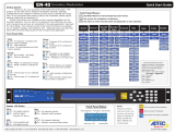
Front Panel
The Function Buttons and Directional Keypad of the EN-100 are used to configure and
monitor the signal input and output of the device.
Front Panel LCD Quick Views
There are several Quick Views that can be accessed via the front panel LCD by
pressing the up and down arrows.
1) Service Data: When in normal encoding mode, the LCD will display the following
information: TS Mux Rate, Conditional Access Mode, Service ID Number, Service Name, and
Service Provider.
2) Encoding Status: This quick view displays the Input and Output Resolution, Frame
Rate, Input interface, SDI interface Mode, and Bars/Tones/ID status.
3) Video Status: This quick view displays the Video PID, CODEC, Chroma Type, Bit depth,
Video Bitrate, Entropy Coding, and Video Autofill status.

4) Audio Status: This quick view displays the Audio Codec type, Encode or Pass Through
Rate, Encode or Passthrough mode.
5) Audio PIDS: This quick view displays the Audio PIDs for all 8 pairs of audio.
6) TSoIP State: This quick view displays the status of IP Transport mode, RTP, FEC mode,
and Multicast Connector. Up to 4 destination IP addresses can be sent simultaneously.
7) Modulator State*: This quick view displays the RF Tx status if the unit is equipped with
optional modulator.
8) ASI Remux State: This quick view displays the status of ASI Remux status if the
feature is enabled.

Transport LED Indicators
Indicator
Function
Video
Off - If modulator is installed, an off led indicates that no video is detected on
the selected input or that ASI Receive mode is enabled.
On - Video is detected on the selected input.
Blink - No video is detected and fault mode is active.
Encode
Off - Device is not encoding. Idle State
On - Device is encoding.
AVC
Off - Set to MPEG2 Encoding
On - Set to H.264 (Advanced Video Coding) Encoding
Note: MPEG2 encoding ony available with EN100-VE2-01 option
4:2:2
Off - Encoding chroma type 4:2:0.
On - Encoding chroma type 4:2:2.
10-bit
Off - Encoding bit depth of 8
On - Encoding bit depth of 10
Note: 10-bit encoding only available with EN100-VE2-01 option and in AVC
mode
IP Out
Off - Transport of IP via Ethernet or GigE is idle.
On - Transport of IP via Ethernet or GigE is active.
RF Out
Off - Modulator is not transmitting.
On - Modulator is transmitting.
Blink - Modulator is running in test mode.
Note: Making changes to specific modulator parameters can cause the
modulator to stop transmitting and you will need to re-enable it. This is by
design to prevent transmission with an incorrect power setting.
OTT
Off - Over The Top transmission not enabled
On - Over The Top transmission enabled
Note: Available on future release
Audio Encode Indicators
Indicator
Function
A1 through
A8
Off - Audio encoder configuration is set to off.
On - Audio encoder configuration is set to encode or passthru.
Note: This product offers optional extended audio encoding of the upper
four pairs. If you experience issues engaging the upper pairs, check your
feature keys first.

System Indicators
Indicator
Function
Alarm
Off - No system alarms.
On - System alarm.
(Typically NTP alarm)
BISS
Off - Service is not encrypted “Clear - Free to air”
On - Service is Encrypted “Cyphed - Selected BISS mode”
Link
Off - No network detected
On - Network communication active
Busy
Off - No network activity
On - Network traffic present
Controls
Using the Mode, Select, Enter, Escape, and directional buttons, the user can control the unit
via the front panel.
Control
Function
Mode button
Mode will cycle you through top layer menus.
Select
Select will enter you into edit mode.
Enter
Enter submits any edits.
Escape
Escape returns you to the previous menu layer.
Cursor Arrows
Arrows will navigate you within submenus
Programming
Keypad
For value entry. F2 functions as a “.” decimal or period.

Modulator Lineup
This feature enables the operator to quickly view and/or configure select modulator RF
output parameters. The parameters available in this menu are;
1. Carrier Mode: [ PURE_CARRIER or MODULATED]
2. Transmit: [ ENABLED or DISABLED]
3. Output Power: [ in 0.5dB increments ]
4. Output Frequency: [ in 1.0MHz increments ]
To access the menu, press the F1 and F2 keys simultaneously. The front panel will briefly
flash “MODULATOR LINEUP” then display the menu.
Note: To use this feature, the front panel display must be illuminated. If the display is
dim, press ANY front panel button to illuminate it.
Note: If the unit has been previously configured by the operator and powered OFF and ON,
then the display will read the last valid configuration, however, Tx will read DISABLED.
To select the desired Carrier Mode, press the front panel “SELECT” button.
To set Transmit to ENABLED or DISABLED, press the front panel “ENTER” button.
To set the desired output Power Level, press and hold the front panel ↑ or ↓ button.
To set the desired output Modulator Frequency, press and hold the front panel ← or →
button.
Note: If the Modulator Frequency is reconfigured when Transmit = ENABLED, then Transmit
will be automatically set to DISABLED.

Front Panel Menu Structure
1.Services Menu
Item
Function
Options
1.1
TS Mux
Rate
Transport Mux Rate is the total transport
stream rate. Use this number to match total
circuit throughput
1000000 - 150000000
note: The actual lower limit
is configuration dependent.
1.2
ABR Mode
The Adaptive Bit-rate mode allows the
encoder to adjust TMR and Video bit-rate
without performing an encoder restart. This
mode is useful for dynamic bandwidth based
solutions.
When this configuration is set to OFF, the
default configuration, bit-rate changes to
TMR or Video rate will restart the encoder if
required. With this configuration set to
Instant, bit-rate changes to TMR or Video
rate will not restart the encoder.
Note: With this mode enabled, a transport
stream analyzer will show a PCR accuracy
error on TMR changes. This is a type of "false
alarm" if the error occurs during a bit-rate
transition, the decoder adapts dynamically to
the change.
OFF
Instant
1.3
Program
Number
Sets the program number in the PAT
(Program Association Table). This value can
be set in hexadecimal and decimal format.
1 - 65535
0x0001 - 0xFFFF
1.4
Service
Name
Identifies the service by name. This value is
used to populate either the DVB SDT table, or
ATSC VCT table. You are limited to 20
characters in DVB mode and 7 in ATSC mode.
When using Bars, Tones and ID overlays, this
field is displayed as part of the service
information.
1- 20 ascii characters in
DVB mode
1-7 ascii characters in ATSC
mode
1.5
Service
Provider
Identified the services provider. This value is
used to populate either the DVB SDT table, or
ATSC VCT. When using Bars, Tones and ID
overlays, this field is displayed as part of the
service information.
1-20 ascii characters in DVB
mode
1-20 ascii characters in
ATSC mode
1.6
Tables
Allows the operator to choose which type of
Tables the encoder will generate.
DVB
ATSC

DVB - includes PMT, PAT, NIT and SDT tables
MPEG - includes PAT and PMT tables
ATSC - includes PAT, PMT, VCT, RRT, MGT,
and STT tables
DVBSDTONLY - includes PMT, PAT, and SDT
tables
MPEG
DVBSDTONLY
1.7
ASI
Receive
Mode
Routes a external ASI signal from the HD/SDI
input in the place of the internally encoded
signal.
ON
OFF
1.8
ASI Mode
Configures the ASI output ports transmit
mode.
When set to Continuous, Data is transmitted
at the configured TMR rate continuously
regardless of whether or not there is a valid
video source.
When set to Encode only, data will only be
transmitted if there is a valid video source.
Data will not be transmitted if the encoder is
idling.
CONTINUOUS
ENCODE ONLY
1.9
ASI
Reserve
Set the reserve bandwidth for ASI Remux
Note: Setting to zero disables ASI Remux
0-100Mb/s
1.10
Carrier ID
Menu
Carrier ID contains unique information within
the transport stream to aid in identifying and
troubleshooting satellite sources. Specified by
SUIRG and endorsed by the WBU-ISOG, the
user will need to complete some fields. The
Encoder Manufacturer and Encoder Serial
Number fields will automatically be filled.
Provider ID: 5 characters.
Phone: 17 Character
number ( typically operator
MCR/POC number. '+','(',
and ')'.
Longitude: 9 Characters
('+000.0000' to
'+/-180.0000')
Latitude: 8 Characters
('+00.0000' to
'+/-90.0000')
User Information: 15
characters.
1.11
Bars,
Tones, ID
Menu
Bars, Tones and Service ID information can
be overlayed on top of valid video by
selecting the desired combination from this
menu.
Note: When an audio input / channel is
configured for Pass through operation
Internal tone generation does not function for
the pass through channels.
Bars Mode: ON, OFF
Bars Type: BARS, Solid
color, FLASH
Tones Mode: ON, OFF
OSD Mode: ON, OFF, BLINK

2. RF Tx Menu
Note: This menu is dynamic. It will only appear if you unit has factory installed modulator
option.
Item
Function
Options
2.1
Transmit
Allows the operator to enable or
disable the Main RF output. If
Transmit is enabled and any value
for Type, Frequency, Rolloff,
Symbol Rate, or Interface Rate is
changed, then Transmit will be
automatically disabled. However,
the monitor output will remain
active.
Disable
Enable
2.2
Type
Allows the selection of the mod
type.
DVBS
DVB-S2
DVB-S2X
2.3
Mode
This control allows the operator to
select the desired modulation mode
and FEC code rate.
We display all possible ranges
available via our device in the Front
Panel. This list will differ from the
list found in the web UI as it only
shows those options available based
on the feature keys found.
QPSK-1/2
QPSK-2/3
QPSK-3/4
QPSK-5/6
QPSK-6/7
QPSK-7/8
QPSK-1/4
QPSK-1/3
QPSK-2/5
QPSK-3/5
QPSK-4/5
QPSK-8/9
QPSK-9/10
QPSK-13/45
QPSK-9/20
QPSK-11/20
QPSK-11/45
QPSK-4/15
QPSK-14/45
QPSK-7/15
QPSK-8/15
QPSK-32/45
8APSK-5/9-L
8APSK-26/45-
L
16APSK-5/6
16APSK-8/9
16APSK-9/10
16APSK-7/15
16APSK-8/15
16APSK-32/45
16APSK-1/2-L
16APSK-8/15-L
16APSK-5/9-L
16APSK-26/45
16APSK-3/5
16APSK-3/5-L
16APSK-28/45
16APSK-23/36
16APSK-2/3-L
16APSK-25/36
16APSK-13/18
16APSK-7/9
16APSK-77/90
32APSK-3/4
32APSK-4/5
32APSK-5/6
32APSK-8/9
32APSK-9/10
32APSK-2/3-L

8PSK-3/5
8PSK-2/3
8PSK-3/4
8PSK-5/6
8PSK-8/9
8PSK-9/10
8PSK-23/36
8PSK-25/36
8PSK-13/18
8PSK-7/15
8PSK-8/15
8PSK-26/45
8PSK-32/45
16QAM-3/4
16QAM-7/8
16APSK-2/3
16APSK-3/4
16APSK-4/5
32APSK-32/45
32APSK-11/15
32APSK-7/9
32APSK 2/3
64APSK-32/45-L
64APSK-11/15
64APSK-7/9
64APSK-4/5
64APSK-5/6
128APSK-3/4
128APSK-7/9
256APSK-29/45-
L
256APSK-2/3-L
256APSK-31/45-
L
256APSK-32/45
256APSK-11/15-
L
256APSK-3/4
2.4
Local
Oscillator
Determines the Local Oscillator
Frequency (in Mhz) variable in the
embedded Uplink Calculator.
For Normal (Non-Inverted)
Spectrum Mode:
Freq
Modulator
= Freq
Uplink
- Freq
Local
Oscillator
For Inverted Spectrum Mode:
Freq
Modulator
= Freq
Local Oscillator
-
Freq
Uplink
Note:This field is provided for
convenience purposes only and to
aid in the automatic calculation of
the Modulator frequency. The
actual setting will depend on your
external hardware (Block
Upconverter), and
may differ
from
the value set in here.
User defined
2.5
Uplink
Frequency
Determines the Uplink Frequency
(in Mhz) variable in the embedded
Uplink Calculator.
Note:This field is provided for
convenience purposes only and to
aid in the automatic calculation of
the Modulator frequency. The
User Defined

actual setting will depend on your
external hardware (Block
Upconverter), and
may differ
from
the value set in here.
2.6
Frequency
(Read Only)
Allows the operator to enter the
desired output frequency of the
main RF output port.
950MHz - 2.15GHz L-BAND
50MHz - 180MHz IF
** The monitor output frequency for
the EN-XX IF is fixed at 1.080GHz.
The monitor output frequency for
the EN-XX L-Band tracks with the
main RF output frequency.
2.7
Power
Allows the operator to configure the
output power of the main RF output
port. The monitor output power
level for the EN-XX IF and L-Band is
fixed at -45dBm. Power is defined
as the composite power referenced
to an un-modulated (Pure Carrier)
carrier.
-35 to +5dBm LBAND
-30 to +5dBm IF
2.8
Spectrum
Inversion
The Spectrum Inversion options are
either Normal or Invert. If Normal
is selected, then spectrum inversion
does not occur. Spectral inversion
can occur when either the
baseband signal is up-converted to
an IF frequency or when the IF is
upconverted to the desired RF
output frequency.
Invert
Normal
2.9
FEC Frame
When operating in DVB-S2, the
Frame Type options are either
Normal or Short. The Normal
64,800-bit FEC frame provides
better protection but introduces
more latency compared to the
Short 16,200-bit FEC frame.
Therefore, the Short FEC frame
type should be selected in
applications where latency is critical
and the longer frame type should
be used to optimize protection.
Short
Normal
2.10
Rolloff
The Rolloff selection will determine
the shape of the output filter. The
occupied bandwidth of the
modulated signal is the symbol rate
multiplied by (1+α) where alpha (α)
is the rolloff factor. By using a
lower alpha, carriers can be spaced
5
10
15
20
25
30

closer together on a given
transponder or an increased symbol
rate can be realized for a given
bandwidth.
2.11
Pilot
When operating in DVB-S2, the
Pilot options are either ON or OFF.
When pilots are enabled, the total
data throughput is reduced by
approximately 3.0%.
On
Off
2.12
Rate Priority
The Rate Priority control allows the
operator to designate which rate
will be kept constant. When the
Symbol Rate is entered and Rate
Priority is Symbol, the symbol rate
is held constant and the Interface
rate is calculated. When the
Interface Rate is entered and Rate
Priority is Interface, the interface
rate is held constant and the
symbol rate is calculated.
Symbol
Interface
2.13
Symbol Rate
The number of symbols transmitted
per second. The amount of data per
symbol is dependant upon the
modulation type, e.g. QPSK, 8PSK,
etc.
Range can be determined by feature
key.
2.14
Interface
Rate
The Interface Rate is the bit rate at
the baseband interface.
Range can be determined by feature
key.
2.15
Carrier Mode
The Carrier Mode control allows the
operator to select ON for normal
operations or select one of four
unmodulated carriers. The Pure
Carrier option will provide an
un-modulated output carrier at the
desired frequency and output
power.
Pure Carrier
Modulated
2.16
10Mhz Clock
Allows operator to generate or pass
a 10Mhz signal. The signal can be
generated internally or sourced
externally.
*** This is a special order option.
If your unit does not have the
functionality the setting will read
“N/A”
OFF
ON
EXTERNAL

2.17
10 Mhz
Clock
Combined
Allows the operator to choose
whether or not to combine the
10Mhz signal with the L-Band
output.
*** This is a special order option.
If your unit does not have the
functionality the setting will read
“N/A”
UNCOMBINED
COMBINED
2.18
PHYSICAL
LAYER
SCRAMBLER
Scrambles all of the PLFRAMES
except for their header.
The PLS signature assumes values in
the range 0, 262141
2.19
MODULATOR
LINEUP
This feature enables the operator to
quickly view and/or configure select
modulator RF output parameters.
Carrier Mode:
PURE_CARRIER or MODULATED
Transmit:
ENABLED or DISABLED
Output Power:
User defined in 0.5dB incr.
Output Frequency:
User defined in 1.0MHz incr.

3. IP Tx Menu
Note: this is a parallel menu. It has four index. Use the left or right arrows to navigate to
desired index.
Item
Function
Options
3.1
Mode
Enables IP Egress.
Off
Send
3.2
IP Tx Mode
Switches from UDP/RTP and TCP
UDP/RTP
TCP
3.3
Tx IP Address
The IP Address of which the
Multicast or Unicast is broadcast.
Multicast addressing supports
the transmission of a single IP
datagram to multiple receivers.
Valid Multicast addressing range
is 224.10.XXX.XXX to
239.XXX.XXX.XXX. Unicast
addressing sends a single IP
datagram to only one receiver.
The Unicast address will be the
unique IP of the receiving
device.
user-defined; numeric field in
format xxx.xxx.xxx.xxx
3.4
Tx Port
port assignment used for
transmitting a multicast
user-defined using the numeric
keypad
3.5
Tx GW Address
The Unicast Gateway
automatically handles IP routing
for unicast transmissions. This
must be configured if the
outgoing unicast requires a
different gateway from the
configured system default
gateway. A route is
automatically added when the
unit is configured for transmit
and a Unicast Gateway exists.
The route is deleted if set to
0.0.0.0 or Multicast Mode set to
OFF.
user-defined; numeric field in
format xxx.xxx.xxx.xxx
3.6
DVB per IP
Configures the amount of DVB
transport stream packets ( 188
bytes per DVB packet ) per IP
packet payload
1
4
7
3.7
RTP
allows for sequence numbering
and timing; editable if Multicast
Mode is set to 'Send'
On
Off

3.8
FEC Mode
Forward Edge Correction; selects
on/off. When selected, sends
two FEC RTP streams in addition
to a source RTP stream enabling
a receiver to reconstruct missing
packets in the source stream.
OFF
ON
MAXBURST
BURST
LOWLATENCY
3.9
FEC L
affects the maximum burst
packet loss that can be
recovered
Note: The product of FEC L and
FEC D cannot exceed a value of
100
4-20
3.10
FEC D
defines latency involved in burst
recovery
4-20
3.11
TOS
Allows the operator to sets the
TOS bits in the IPv4 header of
the TSoIP payload
0 = Normal service
2 = Minimize monetary cost
4 = Maximum reliability
8 = Maximize throughput
16 = Minimize delay
3.12
TTL
Time-to-Live; specifies the
number of iterations or
transmissions the packet can
undergo before it is discarded
user-defined using the numeric
keypad
3.13
Tx Connector
sets the physical connector (on
the rear of the unit) to use for
multicast transmit purposes on
the indicated encode channel.
Ethernet
GigE
/


