Page is loading ...

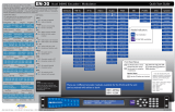
Quick View Status
Quick Start Guide
Thank you for your purchase of the Adtec EN-100 Encoder/Modulator. This
product is sold with optional modulator hardware packages. Configurations and
indicators relevant to those add-on package are noted here. If you purchased this
product without a modulator, please disreguard settings noted with an asterisks.
Adtec Digital US Sales +1-615-256-6619 International Sales +1-904-394-0389 www.adtecdigital.com 2016 Adtec Digital
10-bit / 1080P Multi-CODEC Encoder / Modulator
Front Panel Menus:
Use Mode Button to move
through top layer menus.
Use arrows for navigation
in submenus.
SELECT
ENTER
MODE
Use select to enter into edit
mode and enter to
save selection.
EN-100
Video
On - Video is detected
Blinking - No video is detected
Encode
Off - Device is not encoding
On - Device is encoding
AVC
Off - MPEG 2 is selected for encode
On - MPEG 4 (H.264) is selected for
encode
4:2:2
Off - Encoding chroma type 4:2:0
On - Encoding chroma type 4:2:2
10-bit
Off - Encoding depth of 8-bit
On - Encoding depth of 10-bit
IP Out
Off - IP Egress is idle
On - IP Egress is active
*RF Out
Off - Modulator is not transmitting
On - Modulator is transmitting
Blinking - Modulator is in test mode
OTT
Off - Feature not yet available.
On - Feature not yet available.
Alarm
Off - No system alarms
On - System alarm
BISS
Off - Encryption config is OFF
On - Encryption config is ON
A1 - A8
Off - Not encoding
On - Encoding or Passthru Audio
Blinking - Audio is active but there
is no source
Link
Off - No network detected
On - Connection active
Busy
Off - No network activity
On - Network traffic present
Reset:
Should you need to reset your device, you can do
so via the front panel by pressing the MODE,
ESCAPE and RIGHT ARROW keys simultaneously.
Units ship with the front panel
logged in by default. If you become
logged out and are prompted for a
password, use the following key
sequence for access.
Press <Select> when panel displays
‘User Login -- logged out’
Press <Up arrow>
Press <Select>
Press <Enter>
Press <Right arrow>
Press <Enter>
LED Status
Type Bitrate
Audio 1 - 8
Audio 1:11300 3:11400 5:11500 7:11600
PIDS 2:12300 4:12400 6:12500 8:12600
Audio PIDS 1 - 8
For information on the core systems of the encoder,
use the down arrorw on the front panel to scroll
through these quick view menus.
Encoder Status TMR Encryption
Service ID Service Name Service Provider
ENCODING: 20.000M CAS:BISS_1
SVC: 00001 “Serv. Name” Serv. Provider
1:MU 384k 3:MU 384k 5:MU 384k 7:MU 384k
2:MU 384k 4:MU 384k 6:MU 384k 8:MU 384k
TSoIP 1 - 4
*Modulator Status Mod FEC Power Roll O
Video Bit Rate Entropy Coding Auto Fill
1: SEND ON BUR GIGE 3: SEND OFF OFF GIGE
2: SEND ON OFF GIGE 4: OFF OFF OFF GIGE
Special Keys:
Use the F2 button as a decimal.
F2
Video
Audio
VBI
Input: Resolution Frame Rate Source Mode
Output: Resolution Frame Rate Bars/Tones/ID Status
I /RES: 1920x1080 25i INP: SDI MODE: AUTO
O/RES: 1920x1080 25i B/T/ID: OFF/OFF/OFF
Video PID CODEC Chroma Bit Depth
VID: 481 COD: H.264 CHR: 422 BITD: 10
VRT: 16989000b/s ENT: CABAC A/F: ON
RTP FEC Status Connector
TX: Enable 32APSK_9/10 Pwr: -30dB RO: 25%
Freq: 1291MHz DVB-S2 Sym: 15.00Ms Pilot: ON
Frequency Mode Symbol Rate Pilot
ENCODING:20.000M CAS:BISS_1
SVC:00001“Service Name”Service Provider
Services *RF Tx IP Tx Video Audio PIDS VBI Prole CAS System
<< 1 - 4 >>
Mode
IP Tx Mode
Tx IP Address
Tx Port
Tx GW Address
DVB per IP
RTP
FEC Mode
FEC L
FEC D
Type of Service
TTL
Tx Connector
Source
Closed Cap.
Select
Save
Delete
Login
Duration
Network Menu
Time Menu
NTP Menu
Alarm
SNMP Menu
COM2
Feature Menu
Name
Firmware
Backlight Dim
Transmit
Type
Mode
Local Oscillator
Uplink Freq
Frequency(MHz)
Power(dBm)
Spectrum Invrsn
Fec Frame
Roll O
Pilot
Rate Priority
Symbol Rate
Interface Rate
Carrier Mode
10 MHz Clock
Clock Comb.
Transport ID
PMT PID
PCR PID
Video PID
Audio 1 PID
Audio 2 PID
Audio 3 PID
Audio 4 PID
Audio 5 PID
Audio 6 PID
Audio 7 PID
Audio 8 PID
Teletext PID
AMOL PID
VITC Mode
VITC PID
Splice Mode
Splice PID
Modulation Indicators:
No modulator
IF/LB/10M modulator
There are 2 different encoder modules available for the EN-100 and the unit
can be ordered with either:
VE1 - 1080p AVC 8-bit
VE2 - 1080i Multi-CODEC 10-bit
REMUX: ACTIVE PROGRAMS: 7
INPUT: 038.963Mb/s RESERVED: 040Mb/s
ASI Remux Status Programs on Input
Input Data Reserved Bandwith
Mode
Clear SW
Encrypted SW
User ID 1
User ID 2
TS Mux Rate
ABR Mode
Program Num
Service Name
Service Provider
Tables
ASI Rx Mode
ASI Mode
ASI Reserve
ASI Reserve
Carrier ID Menu
Bars,Tones,ID
<< ENC Select >>
Input
SDI Mode
CVBS Input Mode
CODEC
Entropy Coding
Chroma
Deblock Filter
Video Field Cod.
Video Rate
Autoll
Latency
Latency Trim
Fault Mode
Fault Resolution
Aspect Ratio
AFD
GOP Type
GOP Structure
GOP Size
3-D Sync Mode
<< 1 - 2 >>
Surround Mode
Surround Anchor
<< 1 - 8 >>
Input
Mode
Type
Rate
Level
Analog Level
Sync
MPEG Format
IFB
SDI Pair
SDI Clock Source
ECC Words
Audio Level B

Adtec Digital Technical Support: 615.256.6619 www.adtecdigital.com EN-100 3.00.XX (4/16)
88
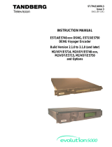
ASI In 75 Ohm terminated ASI per DVB-ASI. Up to 100 Mbps
Encoder
1- 8
Processor
IF Out
MODULATED
To begin, you will need to connect to your EN-100 via ethernet
directly, or by adding the EN-100 to your local area network.The default
address for all Adtec devices is 192.168.10.48.
To connect directly to the device, make sure that your computer
and the device have IP addresses within the same IP class range (ex.
192.168.10.48 for the device and 192.168.10.49 for your computer).
If you need to change the IP address of the device, this can be done via
the front panel, System > Network menu. Using a CAT 5 crossover
cable, connect one end to your computer and the other to the Ethernet
port found on the processor section of the back panel. (Some computers
can auto negotiate the connection and a crossover may not be
necessary.)
To add the device to a LAN, connect a standard CAT 5 Ethernet
cable to your network router and then to the Ethernet port on the back
of the device. If your network is DHCP enabled and you prefer that over
a static IP, you can turn on DHCP for the device via the front panel,
System > Network menu.
Web-Based Control Application
Getting Connected
Adtec Digital has adopted
zero-conguration networking
technology, streamlining the setup and
conguration processes for our products.
The use of this technology enables
automatic discovery of Adtec devices and
services on an IP network. Used in tandem
with the web-based control and
conguration applications we can now
provide 1-click access to any device.
By using the built-in Bonjour
©
locater in
Apple's
©
Safari
©
browser or the plug-ins
readily available for IE
©
or Firefox
©
browsers, users can locate all of the Adtec
devices on a network by referencing the
serial number on the back of the device. Clicking on the unit in the Bonjour
©
list will re-route you to a
login page. If you do not wish to use Bonjour, you can reach the device’s web application by pointing
your browser to the IP Address of the device. Ex. http://192.168.10.48/. You will be prompted for a
username and password. The default username is ‘adtec’. The default password is ‘none’.
The left-hand panel of the application will report current status in real-time while the right
panel tabs will allow you to congure your device.
?
Have questions? Each field or group of fields in
our web-based application has a hint button associate
with it. It contains information on use of the field or
acceptable ranges.
Getting Started
/