Page is loading ...

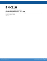
720X480 29i 19.40M
1DD 192K 2DD 192K 48
Front Panel Status
Video Resolution Frame Rate Video Bit Rate
Audio Input 1 & 2 Sampling Rate
Units ship with the front panel
logged in by default. If you become
logged out and are prompted for a
password, use the following key
sequence for access.
Press <Select> when panel displays
‘User Login -- logged out’
Press <Up arrow>
Press <Select>
Press <Enter>
Press <Right arrow>
Press <Enter>
Quick Start Guide
Getting Started
Thank you for your purchase of the Adtec EN-40 Encoder. This
product can be sold with an optional modulation hardware package.
Configurations and indicators relevant to that add-on package are noted
here. If you purchased this product without the modulator, please ignore
settings noted with an asterisks (*).
Further instructions are available via the manual integrated into the
on-board software. You can view it by looking for the HELP tab once your
unit is powered up and you are connected to the web-application. See back
for more details. This manual and the most recent firmware are available
on our support website, www.adtecinc.com. Advanced users can also find
direct API command help as part of the on-board web application.
System LED Status
Alarm
Off - No system alarms.
On - System alarm.
(Typically NTP alarm)
BISS
Off - No encryption set
On - Encryption active
Front Panel Menus:
Use Mode Button to move through top layer menus.
Use arrows for navigation in submenus.
Use select to enter into edit mode and enter to save selection.
Video
Off - If modulator is installed, ASI
Receive mode is enabled.
On - Video detected
Blink - No video detected and Fault
mode is enabled.
Encode
Off - No Encoding - Idle State
On - Device is encoding.
AVC
Off - MPEG 2 is selected for encode.
On - MPEG 4 (H264) is selected for
encode.
4:2:2
Off - Chroma type 4:2:0 is selected
for encode.
On - Chroma type 4:2:2 selected for
encode.
Front Panel LEDs:
Adtec Digital US Sales +1-615-256-6619 International Sales +1-904-394-0389 www.adtecinc.com ©2010 Adtec Digital
SELECT
1
2abc
3def
5jkl
6mno
7pqrs
8tuv
9wxyz
0
4ghi
F1
F2
ENTER
ESCAPE
MODE
4
S
IP Out
RF Out
Bars
IP Out
Off - Transport of IP via Ethernet
or GigE is idle.
On - Transport of IP via Ethernet
or GigE is active.
RF Out *
Off - Modulator is not enabled.
On - Modulator is transmitting.
Blink - Modulator is running in test
mode.
Bars
Off - B/T/ID options are disabled.
On - B/T/ID have been enabled.
A1 - A4
Off - Audio encoder configuration
is set to off.
On - Audio encoder configuration
is set to encode or passthru.
Busy
Off - No network activity
On - Network traffic present
Link
Off - No network detected
On - Network communication active
4
Encoder/Modulator
Encoder
Video
Encoder
Audio
Transmit
PIDs
Table
Prole
System
Login
Duration
Network
Time
NTP
Alarm
COM2
Firmware
Table
VBI Source
Closed Cap.
Service Name
Load
Save
Encrypt.
Mode
Clear Word
Encrypt Word
User ID 1
UserID 2
Auto TMR *
Mux Rate
Vid. AutoFill
IP Destinations 1-4
PCR
Prog. No.
Map PID
Vid. PID
Aud.1 PID
Aud. 2 PID
Aud. 3 PID
Aud. 4 PID
TS ID
AMOL
Splice
VITC Mode
VITC PID
Sample Freq.
A1 A2
A3 A4
Sync
Input
Mode
Type
Bitrate
Volume
Modulator *
Transmit
Mod. Type
Mod. Mode
Frequency
Power
Spec Inv.
FEC Frame
Roll O
Pilot
Rate Prior.
Sym. Rate
Inter. Rate
Carrier Mode
Occ. Band.
Status
Rate
CODEC
Chroma
Input
ASI Rec.
GOP
GOP Str.
GOP Size
Latency
Hue
Brightness
Contrast
Saturation
SELECT
ENTER
MODE
Device contains L-Band modulator
Device contains IF modulator
Device does not contain a modulator
Reset:
Should you need to
reset your device, you
can do so via the front
panel by pressing the
MODE, ESCAPE and
RIGHT ARROW keys
simultaneously.

Power
To begin, you will need to connect to your EN-40 via ethernet
directly, or by adding the EN-40 to your local area network.The default
address for all Adtec devices is 192.168.10.48.
To connect directly to the device, make sure that your computer
and the device have IP addresses within the same IP class range (ex.
192.168.10.48 for the device and 192.168.10.49 for your computer). If
you need to change the IP address of the device, this can be done via
the front panel, System > Network menu. Using a CAT 5 crossover
cable, connect one end to your computer and the other to the Ethernet
port found on the processor section of the back panel. (Some computers
can auto negotiate the connection and a crossover may not be
necessary.)
To add the device to a LAN, connect a standard CAT 5 Ethernet
cable to your network router and then to the Ethernet port on the back
of the device. If your network is DHCP enabled and you prefer that over
a static IP, you can turn on DHCP for the device via the front panel,
System > Network menu.
Web-Based Control Application
Getting Connected
?
Adtec Digital has adopted zero-conguration
networking technology, streamlining the setup and
conguration processes for our products. The use of
this technology enables automatic discovery of Adtec
devices and services on an IP network. Used in
tandem with the web-based control and conguration
applications we can now provide 1-click access to any
device.
By using the built-in Bonjour
©
locater in Apple's
©
Safari
©
browser or the plug-ins readily available for IE
©
or Firefox
©
browsers, users can locate all of the Adtec
devices on a network by referencing the serial number
on the back of the device. Clicking on the unit in the
Bonjour
©
list will re-route you to a login page. If you do
not wish to use Bonjour, you can reach the device’s
web application by pointing your browser to the IP Address of the device. Ex. http://192.168.10.48.
The left panel of the application will report current status in real-time while the right panel tabs will
allow you to congure your device. Additional hints regarding conguration options can be found by clicking on
the hints buttons
associated with each
eld or group of elds.
Adtec Digital Technical Support: 615.256.6619 www.adtecinc.com 10.25.10
Power ...............................................................................................................................
Power 1 & 2 Redundant AC Power, Standard 3 pin computer power plug
(Auto range 70-240 VAC Input)
Modulator (optional)*............................................................................................
Main RF output, 50 Ohm BNC
L-Band Model: Frequency range 950 MHz to 1.750 GHz, Power Level -50 to -7 dBm
IF Model: Frequency range 50 MHz to 180 MHz, Power Level -30 to +5 dBm
Monitor RF output, 50 Ohm BNC
L-Band Model: Fixed power level at -45 dBm
IF Model: Fixed power level at -45 dBm, xed frequency at 1.08 GHz
10MHz Clock BNC 50 Ohm connector for external 10MHz reference input
Processor ......................................................................................................................
GigE MPEG2 or RTP multicast transport egress port (SMPTE 2022)
COM2 API Serial Communication Interface
COM1 Serial Port Used for Troubleshooting (Terminal)
Ethernet 10/100 base T ethernet interface (Monitoring/Management)
USB 2.0 Not Currently Supported
DVC Parport 9-pin parallel I/O interface for control systems
RS422 Not Currently Supported
GPIO Tally and Control Port
Encoder.........................................................................................................................
ASI OUT 75 Ohm source ASI x3 per EN5000839. Up to 100 Mbps.
CVBS In 75 Ohm terminated Standard Denition Composite Video Input
SDI In 75 Ohm terminated Input, Video & Audio (SMPTE 259M for SD & SMPTE 292M for HD) BNC
AES Audio In 1-4 75 Ohm AES-3 per AES3-2003
AES Audio Out 1 Not Currently Supported
Analog Audio In Stereo Pairs 1 and 2 (600 Ohm Balanced)
COM2
Modulator
Processor
ASI Out X 3
C VBS In
SDI In
Encoder
AES Audio
In 1-4
DVC Parport
RS422
GPIO
Analog Audio
GigE
AES Audio Out
Main
Monitor
10Mhz
Clock
COM1
Ethernet
USB
1
2
/