Page is loading ...

sec.4b
−−−−
1
BIBUS 2
nd
Ed. VOP - Technical Manual
SECTION 4B
(REV.I)
APARTMENT
VIDEO DOOR PHONE
STATIONS
ATLANTICO BLACK AND WHITE VIDEO DOOR PHONE 2
SPECIFICATIONS - TECHNICAL SPECIFICATIONS .......................2
ATLANTICO COLOUR VIDEO DOOR PHONE Ref. 1702/40 3
SPECIFICATIONS - TECHNICAL SPECIFICATIONS .......................3
ATLANTICO VIDEO DOOR PHONE 4
ATLANTICO BRACKETS Ref 1202/954 ........................................... 4
INSTALLATION .................................................................................4
PROGRAMMING ..............................................................................5
COLOURED MASK KIT ....................................................................5
ARTICO VIDEO DOOR PHONE Ref. 1705/1 6
SPECIFICATIONS - TECHNICAL SPECIFICATIONS .......................6
ARTICO BRACKETS Ref. 1705/954 .................................................7
INSTALLATION .................................................................................7
PROGRAMMING ..............................................................................7
FRONT GLASS REPLACEMENT ......................................................8
SCAITEL BLACK AND WHITE VIDEO MODULE Ref. 1732/1 9
SPECIFICATIONS - TECHNICAL SPECIFICATIONS .......................9
SCAITEL COLOUR VIDEO MODULE REF. 1732/41 9
SPECIFICATIONS - TECHNICAL SPECIFICATIONS .......................9
SCAITEL VIDEO MODULE 10
SCAITEL VIDEO MODULE BRACKET Ref. 1732/957 ....................10
INSTALLATION ...............................................................................10
TABLE MOUNTED KIT FOR SCAITEL MONITOR Ref. 1732/56 .... 10
UTOPIA COLOUR VIDEO DOOR PHONE Ref. 1703/1 11
TECHNICAL SPECIFICATIONS ......................................................12
BRACKET FOR UTOPIA .................................................................12
INSTALLATION ...............................................................................12
SECTION CONTENTS
ACCESSORIES FOR UTOPIA VIDEO DOOR PHONES .................13
UTOPIA FREE-HANDS COLOUR VIDEO DOOR PHONE 14
SPECIFICATIONS - TECHNICAL FEATURES ................................14
BRACKET FOR UTOPIA Sch. 1703/95 ..........................................15
WALL-MOUNTED VERSION INSTALLATION ................................15
FLUSH-MOUNTED VERSION INSTALLATION ..............................16
INSTALLATION ON PLASTERBOARD WALLS .............................. 18
Volume adjustment .....................................................................19
PROGRAMMING ............................................................................19
Ringer programming and enabling of automatic door opening
system ........................................................................................ 19
Parallel video door phones installation ....................................... 20
Auto-on .......................................................................................20
ACCESSORIES FOR UTOPIA VIDEO DOOR PHONES .................20
Colouredfrontaps ....................................................................20
Handset for hearing-impaired Ref. 1703/137 .............................20
SIGNO BLACK/WHITE VIDEO DOOR PHONE Ref. 1740/1 22
SPECIFICATIONS - TECHNICAL SPECIFICATIONS .....................22
SIGNO COLOUR VIDEO DOOR PHONE 23
SPECIFICATIONS - TECHNICAL SPECIFICATIONS .....................23
SIGNO BRACKETS Ref. 1740/954 .................................................24
INSTALLATION ..............................................................................24
PROGRAMMING ............................................................................25
Parallel video door phone installation ........................................25
Auto-on .......................................................................................25
ARCO BLACK/WHITE VIDEO DOOR PHONE Ref. 1715/1 26
SPECIFICATIONS - TECHNICAL SPECIFICATIONS .....................26
ARCO BRACKETS Ref. 1705/954 ..................................................27
INSTALLATION ..............................................................................27
Parallel video door phone installation ........................................28
Auto-on .......................................................................................28
Download from www.urmet.com Technical Manuals area.

2
−−−−
sec.4b
APARTMENT VIDEO DOOR PHONE STATION
BIBUS 2
nd
Ed. VOP - Technical Manual
ATLANTICO BLACK AND WHITE VIDEO DOOR
PHONE
The Atlantico video door phone implements an electronic call system
and can be used in Bibus 2nd Ed. VOP systems when equipped with
thespecicbracket.
The call volume (to dedicated speaker) can be adjusted in linear
fashion and muted.
Thevideodoorphoneiseasytoinstallbecausenomasonryworkis
needed and all connections are made to the bracket on which the
video door phone will eventually be fastened. The handset connection
is particularly ergonomic. A simple telephone plug is used.
The door opener button by the side of the handset is lit up when the
monitor is on.
The Atlantico video door phone has innovative simple, essential
designed fashioned by Michele De Lucchi and is available in 3
version.
White colour Ref. 1702/1
Anthracite colour Ref. 1702/41
High tech grey colour Ref. 1702/42
ThefrontmaskcolourcanbechangedwiththekitRef.1702/50tosuit
the video door phone for all architectural contexts.
The video door phone Ref. 1702/17 is set up to a speaker
capable interfacing with hearing aids by means of the “T”
function.
•
•
•
218 mm 80 mm
220 mm
Door opener button
Call volume control and adjustment
/
Mute function
Auxiliar
y
buttons
Contrast adjustment
Brightness adjustment
SPECIFICATIONS
The main characteristics of the video door phone are:
Flat4”blackandwhitevideomodule.
Adjustable and mutable call volume. The adjustment wheel appears
red when the volume is muted.
When volume is set to “MUTE” the video door phone will not ring
but the video module will light up.
Door opener button is lit up and green when video module is on.
Service buttons
( and )
for activating, for example, supplementary
electricallocks,staircaselights,monitorauto-onfunction,etc.
Adjustable brightness and contrast.
TECHNICAL SPECIFICATIONS
Power voltage: 16 ÷ 18,5Vdc
Workinguptake: max 0,35A
Stand-by: 0A
Workingpower: max 6,5W
CCIR version Vertical frequency: 50Hz ± 2Hz
Horizontal frequency: 15625 ± 300Hz
Video signal: 1Vpp 75 Ω nominal
1Vpp. -6dB minimum
Kinescope: 4” at 13mm neck
Phosphorous: P45
Screen size: 81 x 59mm
Geometric distorsion: vertical 5% max.
horizontal 5% max.
barrel 10% max.
Brightness: 170cd/m
2
max. setting
X-rays: none
Switch-on delay: 4 sec. max.
Transmitting capsule: electret microphone
Receiving capsule: 45Ω speaker
Button voltage: 24Veff. max.
Button current: 1,2Aeff.
Operating temperature range: -5° ÷ +50°C
Max. humidity: 90%RH
•
•
§
•
•
•
•
•
•
•
•
•
•
•
•
•
•
•
•
•
•
•
•
•
•
ATLANTICO BLACK AND WHITE VIDEO DOOR PHONE
SPECIFICATIONS - TECHNICAL SPECIFICATIONS
-
ATLANTICO BRACKETS
ATLANTICO BLACK AND WHITE VIDEO DOOR PHONE
UNTIL
EXHAUSTION

sec.4b
−−−−
3
APARTMENT VIDEO DOOR PHONE STATION
BIBUS 2
nd
Ed. VOP - Technical Manual
ATLANTICO COLOUR VIDEO DOOR PHONE
Ref. 1702/40
The Atlantico video door phone is a colour apartment station which
can be used in Bibus 2nd Ed. VOP systems when equipped with the
specicbracket.
As the black and white version, also thismodel hasadjustable call
tone volume and muting functions.
Thevideodoorphoneiseasytoinstallbecausenomasonryworkis
needed and all connections are made to the bracket on which the
video door phone will eventually be fastened. The handset connection
is particularly ergonomic. A simple telephone plug is used.
The video door phone is only white but the front part can be customised
byreplacingthestandardframe(blue)withoneoftheveframesfrom
theRef.1702/50kit.
The video door phone Ref. 1702/47 is set up to a speaker
capable interfacing with hearing aids by means of the “T”
function.
SPECIFICATIONS
The main characteristics of the video door phone are:
Flat 4” LCD colour module.
Adjustable and mutable call volume. The adjustment wheel appears
red when the volume is muted.
When volume is set to “MUTE” the video door phone will not ring
but the video module will light up.
Door opener button is lit up and green when video module is on.
Service buttons
( and
)foractivating,forexample,supplementary
electricallocks,staircaselights,videodoorphoneauto-onfunction,
etc.
Adjustable brightness and colour.
•
•
§
•
•
•
TECHNICAL SPECIFICATIONS
Power voltage: 16 ÷ 18.5Vdc
Workinguptake: max. 0.35A
Stand-by: 0A
Workingpower: max. 6.5W
CCIR version: Vertical frequency: 50Hz ± 2Hz
Horizontal frequency: 15625 ± 300Hz
Video signal: 1Vpp 75 Ω nominal
1Vpp -6 dB minimum
LCD: 4” back-lit
Screen size: 81 X 59mm
Resolution: 380H x 250V pixel
Colour system: PAL
Switch-on delay: 4 sec. max.
Transmitting capsule: electret microphone
Receiving capsule: 45Ω speaker
Button voltage: 24Veff. max.
Button current: 1.2Aeff
Operating temperature range: -5° ÷ +50°C
Max. humidity: 90% RH
•
•
•
•
•
•
•
•
•
•
•
•
•
•
•
•
•
ATLANTICO COLOUR VIDEO DOOR PHONE Ref. 1702/40
SPECIFICATIONS - TECHNICAL SPECIFICATIONS
218 mm
80 mm
220 mm
Door opener button
Call volume control and adjustment
/
Mute function
Auxiliar
y
buttons
Colour adjustment
Brightness adjustment
ATLANTICO COLOUR VIDEO DOOR PHONE
Ref. 1702/40
UNTIL
EXHAUSTION

4
−−−−
sec.4b
APARTMENT VIDEO DOOR PHONE STATION
BIBUS 2
nd
Ed. VOP - Technical Manual
ATLANTICO BRACKETS Ref. 1202/954
Atlantico video door phone are provided without fastening bracket
which must be purchased separately.
BracketforBibusII^ed.VOPsystems Ref. 1202/954
ThefollowingfunctionsareofferedbyusingbracketsRef.1202/954in
combination with Atlantico video door phones:
Non-polarised video input.
VideoconnectionwithoordistributorRef.1074/54.
In/out video connection.
Possibility of connecting an additional video door phone.
Privacy function.
6 two-tone ringers (the installer can select the door phone call and
oorcalltones).
BRACKET TERMINALS
VPI
}
VOP signal input
VPI
VPU
}
VOP signal input
VPU (forin-outorparallelvideodoorphoneconnection)
L1
}
Door phone bus
L2
C1
}
Floor call
C2
S+
}
Call repeat wires
S-
Important:Nevertthevideoterminalresistors.
TECHNICAL SPECIFICATIONS
Max.VPIuptakewithvideodoorphonetted: 450mA
Stand-byuptake(L1,L2): 1.6mA max.
Temperature: -5 ÷ +45°C
INSTALLATION
The device can be wall-mounted (on a bracket) or rested on a
horizontalsurfacebyusingthespecictabletopstandinadditionto
thebracket.
WALL-MOUNTED VERSION
1) Arrangetheductsothatitendsincorrespondencewithoneofthe
input holes.
2) Fastenthebrackettothewallattheheightfromtheoorshown
by means of the four screws.
3) Set the switch (on back of video door phone) to position “B”
beforettingthevideodoorphone.
4) Connectthewirestothespecicterminals
5) ExtracttheretainerhookA by inserting the tip of a screwdriver
andpullingthehookdownwards.
6) Fasten the video door phone to the bracket as shown in the
gure.
7) Fasten the video door phone by pushing the retainer hook A
upwards.
•
•
•
•
•
•
•
•
•
•
TABLETOP VERSION
Atlantico can be table-mounted using the specic kit Ref. 1702/92
containing:onetabletopstand,onesocketandonecord.
Proceed as follows:
1) Insertthewirefromthejunctionboxthroughtherearholeofthe
support and fasten it using the U-bolt and the screw provided.
2) Connectthe junction box wires tothe specicterminals onthe
bracket.
3) Settheswitch(onthevideodoorphonerear)onpositionB.
4) ExtracttheretainerhookA from the video door phone.
5) Fitthevideodoorphoneonthebracketandfastenitbypushing
thehookA up.
6) Connectthesystemwirestothecorrespondingsocketterminals.
Consider the following correspondence between terminals when
using the table mounting kit in Bibus 2nd edition VOP systems:
Table mounting kit Bracket
Ref. 1702/92 Ref. 1202/954
R1 ................... → ......................VPI
R2 ................... → ......................VPI
X1 ................... → ...................... L1
X2 ................... → ...................... L2
Y1 ................... → ......................C1
Y2 ................... → ......................C2
Important: The table mounting kit Ref. 1702/92 may be used for
installing video door phones without in/out connection to other
devices.
§
A
B
A
1,55 m
Bracket
A
B
ATLANTICO VIDEO DOOR PHONE
ATLANTICO BRACKETS Ref. 1202/954
INSTALLATION
A
B
ATLANTICO VIDEO DOOR PHONE

sec.4b
−−−−
5
APARTMENT VIDEO DOOR PHONE STATION
BIBUS 2
nd
Ed. VOP - Technical Manual
PROGRAMMING
The procedure for programming video door phone user codes is the
same as for Bibus 2nd edition door phones. Go to the apartment, press
thedooropenerbuttonandpickupthevideodoorphonehandsetafter
settingupthevideodoorphonebookingsequenceonthecallstationor
concierge switchboard.
Release the video door opener button and hang up.
The door phone will sound to indicate that it has been programmed.
RINGER PROGRAMMING
1. Releasethevideodoorphonefromthebracket.
2. Move jumper W1 from position “a” to position “b”.
3. Re-fasten the video door phone.
4. Press the auxiliary service button. The door phone tone will
change each time the button is pressed. Go to the next step once
the ringer has been selected.
5. Press the concierge call button. Theoorcallringer will change
each time the button is pressed. Go to the next step once the
ringer has been selected.
6. Releasethevideodoorphonefromthebracket.
7. Return jumper W1 to position “a”.
8. Re-fasten the video door phone.
PARALLEL VIDEO DOOR PHONE INSTALLATION
A conguration of up to two video door phones in parallel can be
obtained without the addition of local power units (refer to the VOP
1074/20videopowerunitinstructionbookletforwiring).Adoorphone
with additional self-powered ringer may be added to the two video
door phones in parallel.
Operation is described below. Both video door phones (and the door
phoneconnectedinparallelwhererelevant)ringwhenacallisreceived
but only the “master” video door phone (i.e. the one connected directly
tothecolumnortotheVOPextension)willlightup.
The picture can be seen on the video door phone which is off from
thistimeuntiltheprogrammedcallstationoff-hooktime-out(typically
40seconds)bypressingtheconciergecallbuttonwithoutpickingup
the handset.
Thehandsetofeitherofthetwovideodoorphonescanbepickedup
toestablishacommunicationwiththedoorunitanddenitelycapture
the picture.
The oor call button must be connected to a single video door
phone.
AUTO-ON
Video or audio/video auto-on from the MAIN station 1 is possible. With
the door phone standing by, press the concierge call button without
pickingupthehandset.Nothingwillhappenifthemainstation1has
either a conversation in progress or is busy; otherwise, the video door
phone will ring and the video door phone will light up. The door can be
openedandavoiceconnectioncanbeestablishedbypickingupthe
handsetwithintheoff-hooktime-out(typically40seconds).
§
COLOURED MASK KIT
Thevideodoorphonecanbecustomisedbyreplacingthefrontmask
andadd-onnametagwiththosecontainedintheRef.1702/50kit.
Thekitcontainsmasksandcardsofthefollowingcolours:
Yellow
Pink
Grey
Green
Blue
Other media, such as photographs or wall paper, can be used to
customise the video door phone instead of theRef. 1702/50kit. In
this case, use one of the frames provided as a template to trace the
exactinstallationprole.
•
•
•
•
•
(a)
(b)
4 mm slot screwdriver
rotary movement
A
B
C
D
3
1
2
E
ATLANTICO VIDEO DOOR PHONE
PROGRAMMING - COLOURED MASK KIT
ATLANTICO VIDEO DOOR PHONE

6
−−−−
sec.4b
APARTMENT VIDEO DOOR PHONE STATION
BIBUS 2
nd
Ed. VOP - Technical Manual
ARTICO VIDEO DOOR PHONE Ref. 1705/1
Artico offers the most modern technology applied to picture display
and the best quality/price ratio. These features make the video
door phone suitable for normal communication needs and security
applications in video door phone systems.
Thanks to the use of a functional at 4” screen which reduces the
protrusion from the wall, Artico can be installed on the wall without
theneedformasonrywork.
Connectionofthisvideodoorphonearealsosimpleandrapid,thanks
totheterminalboardarrangedonthededicatedbracket.
The video door phone Ref. 1705/17 is set up to a speaker
capable interfacing with hearing aids by means of the “T”
function.
SPECIFICATIONS
The main characteristics of the video door phone are:
Flat4”LCDblackandwithevideomodule.
Adjustable and mutable call volume. The adjustment wheel appears
red when the volume is muted.
Door opener button dedicated.
One service button ( )whichcanbeused,forexample,toswitch
onthestaircaselightsoropenanadditionallock.
One button for calling the concierge station and auto-on ( ):
Doorunit:pickupthehandsetandpressthebutton.
Auto-on:pressthebuttonwithoutpickingupthehandset.
Two potentiometers for adjusting picture brightness and contrast.
•
•
•
•
•
•
A Door opener button.
B1 Auxiliary button: used for special functions.
B2 Auxiliary button: used for calling the concierge station and auto-
on.
C Contrast adjustment control.
D Brightness adjustment control.
E Call volume control and adjustment: turntheknobasfarasit
willgo(redpartvisible)tomutethecalltone(“MUTE”function).
TECHNICAL FEATURES
Power voltage: 16 ÷ 18,5Vdc
Workinguptake: max 0,6A
Workingpower: max 10W
CCIR Version Vertical frequency: 50Hz ± 2Hz
Horizontal frequency: 15625 ± 300Hz
Video signal: 1Vpp 75Ω nominal
1Vpp -6dB minimum
Kinescope: 4” tipo FLAT 20mm neck
Phosphorous: P45
Geometric distorsion: vertical 5% max
horizontal 5% max
barrel 10% max
Brightness: >100cd/m
2
max. setting
X-rays: none
Switch-on delay: 7 sec. max
Transmitting capsule: electret microphone
Receiving capsule: speaker 45Ω
Button voltage: 24Veff. max
Button current: 1,2Aeff
Operating temperature range: -5° ÷ +50°C
Max. humidity: 90% UR
ARTICO VIDEO DOOR PHONE
ARTICO VIDEO DOOR PHONE Ref. 1705/1
SPECIFICATIONS - TECHNICAL FEATURES
Ref. 1705/1
MUTEMEDMAX
200 mm
241 mm
83 mm
A
B1
B2
C ED
UNTIL
EXHAUSTION

sec.4b
−−−−
7
APARTMENT VIDEO DOOR PHONE STATION
BIBUS 2
nd
Ed. VOP - Technical Manual
ARTICO BRACKETS Ref. 1705/954
Articovideodoorphoneisprovidedwithoutfasteningbracketwhich
must be purchased separately.
BracketforBibusII^ed.VOPsystems Ref. 1705/954
ThefollowingfunctionsareofferedbyusingRef.1705/954bracketsin
combination with Artico monitors:
Non-polarised video input.
VideoconnectionwithoordistributorRef.1074/54.
In/out video connection.
Possibility of connecting an additional monitor.
Privacy function.
6 two-tone ringers (the installer can select the door phone call and
oorcalltones).
BRACKET TERMINALS
VPI
}
VOP signal input
VPI
VPU
}
VOP signal input
VPU (forin-outorparallelvideodoorphoneconnection)
L1
}
Door phone bus
L2
C1
}
Floor call
C2
S+
}
Call repeat wires
S-
Important:Nevertthevideoterminalresistors.
TECHNICAL SPECIFICATIONS
Max.VPIuptakewithmonitortted: 700mA
Stand-byuptake(L1,L2): 1.6mA max.
Temperature: -5 / +45°C
INSTALLATION
Arrange the duct so that it ends in correspondence with the input hole
onthebracketandproceedasfollows:
1 Fastenthebrackettothewallattheheightfromtheoorshown
by means of the four screws.
2 Connectthewirestothespecicterminals.
3 Settheswitch(onbackofmonitor)toposition“B”beforetting
the monitor.
4 Extracttheretainerhook A by inserting the tip of a screwdriver
andpullingthehookdownwards.
5 Fastenthemonitortothebracket.
6 FastenthemonitorbypushingtheretainerhookA upwards.
•
•
•
•
•
•
•
•
•
•
PROGRAMMING
The procedure for programming video door phone user codes is the
same as for Bibus 2nd edition door phones. Go to the apartment,
press the door opener button and pick up the video door phone
handsetaftersettingupthevideodoorphonebookingsequenceon
the call station or concierge switchboard.
Release the video door opener button and hang up.
The door phone will sound to indicate that it has been programmed.
RINGER PROGRAMMING
1. Releasethemonitorfromthebracket.
2. Move jumper W1 from position “a” to position “b”.
3. Re-fasten the monitor.
4. Press the auxiliary service button. The door phone tone will
change each time the button is pressed. Go to the next step once
the ringer has been selected.
5. Press the concierge call button. Theoorcallringer will change
each time the button is pressed. Go to the next step once the
ringer has been selected.
6. Releasethemonitorfromthebracket.
7. Return jumper W1 to position “a”.
8. Re-fasten the monitor.
PARALLEL MONITOR INSTALLATION
A conguration of up to two video door phones in parallel can be
obtained without the addition of local power units (refer to the VOP
Ref.1074/20videopowerunitinstructionbookletforwiring).Adoor
phone with additional self-powered ringer may be added to the two
video door phones in parallel.
ARTICO VIDEO DOOR PHONE Ref. 1705/1
ARTICO BRACKETS Ref. 1705/954 - INSTALLATION
PROGRAMMING
ARTICO VIDEO DOOR PHONE
Ref. 1705/1
A
B
A
1
2
3
4
5
O
N
1
2
O
N
D
I
P
Ref. 1705/1
1,55 m
SENTRY+
(a)
(b)

8
−−−−
sec.4b
APARTMENT VIDEO DOOR PHONE STATION
BIBUS 2
nd
Ed. VOP - Technical Manual
Operation is described below. Both video door phones (and the
doorphoneconnectedinparallelwhererelevant)ringwhenacallis
received but only the “master” monitor (i.e. the one connected directly
tothecolumnortotheVOPextension)willlightup.
The picture can be seen on the monitor which is off from this time
until the programmed call station off-hook time-out (typically 40
seconds) by pressing the concierge call button without picking up
the handset.
Thehandsetofeitherofthetwovideodoorphonescanbepickedup
toestablishacommunicationwiththedoorunitanddenitelycapture
the picture.
The oor call button must be connected to a single video door
phone.
AUTO-ON
Video or audio/video auto-on from the MAIN station 1 is possible. With
the door phone standing by, press the concierge call button without
pickingupthehandset.Nothingwillhappenifthemainstation1has
either a conversation in progress or is busy; otherwise, the video door
phone will ring and the monitor will light up. The door can be opened
andavoiceconnectioncanbeestablishedbypickingupthehandset
withintheoff-hooktime-out(typically40seconds).
§
FRONT GLASS REPLACEMENT
The video door phone can be customised by replacing the front
glass.
The following colours are available:
• Smokygrey Ref. 1705/101
(pre-tted on the video door phone)
• Blue Ref. 1705/102
ARTICO VIDEO DOOR PHONE Ref. 1705/1
FRONT GLASS REPLACEMENT
A B
C D
ARTICO VIDEO DOOR PHONE
Ref. 1705/1

sec.4b
−−−−
9
APARTMENT VIDEO DOOR PHONE STATION
BIBUS 2
nd
Ed. VOP - Technical Manual
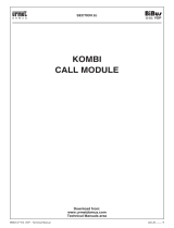
SCAITEL BLACK AND WHITE VIDEO MODULE
Ref. 1732/1
TheScaitelvideomoduleRef.1732/1hasa4”atscreenblackand
white monitor and can be used in combination with switchboards
Ref. 1072/42 so that the operator can see visitors.
SPECIFICATIONS
Availableinmattewhiteplastic(ABS)only,thedeviceisequippedwith
two potentiometers for adjusting picture brightness ( )andcontrast
( ).
Thevideomodulecanbeinstalledtothewallbymeansofabracket
with connector and terminal board.
The monitor can be table-mounted using a specic transformation
kit.
TECHNICAL SPECIFICATIONS
Power: 16 ÷ 18.5Vdc
Consumption: 0.35A max. working
0mA stand-by
Power: 6.5W max. working
CCIR version: Vertical frequency: 50Hz ± 2Hz
Horizontal frequency: 15625 ± 400Hz
Resolution: 400 lines in middle of screen
Video input: 1Vpp-75Ohm nominal
1Vpp -6dB min.
Kinescope: 4” at
Phosphorous: P45
Screen size: 81 x 59mm
Geometric distortion: vertical 8% max. - horizontal 12% max.
Brightness: 170cd/m
2
max. setting
Workingtemperaturerange: - 5 + 45°C
Storage temperature range: -20 + 60°C
Humidity: 90 % RH max.
167 mm
220 mm
56 mm
Contrast adjustment
Bri
g
htness ad
j
ustment
SCAITEL COLOUR VIDEO MODULE
Ref. 1732/41
The Scaitel colour video module Ref. 1732/41 can be exclusively
combined to a switchboard so that concierge personnel can see
visitors.
SPECIFICATIONS
Availableinmattewhiteplastic(ABS)only,thedeviceisequippedwith
two potentiometers for adjusting picture brightness ( ) and colour
( ).
The monitor (basic or with add-on modules) can be table-mounted
usingaspecictransformationkit.
TECHNICAL SPECIFICATIONS
Power voltage: 16 ÷ 18.5Vdc
Workinguptake working: 0.35A max.
stand-by: 0mA
WorkingPower: 6.5W max
CCIR version: Vertical frequency: 50Hz ± 2Hz
Horizontal frequency: 15625 ± 400Hz
Resolution: 480H x 234V
Video input: 1Vpp-75Ohm nominal 1Vpp -6dB min.
Kinescope: 4” TFT
Colour system: PAL
Screen size: 81 x 59mm
Workingtemperaturerange: -5 + 45°C
Storage temperature range: -20 + 60°C
Humidity: 90% RH max
167 mm
220 mm
56 mm
Colour adjustment
Bri
g
htness ad
j
ustment
SCAITEL BLACK AND WHITE VIDEO MODULE Ref. 1732/1
SPECIFICATIONS
SCAITEL COLOUR VIDEO MODULE Ref. 1732/41
SPECIFICATIONS
SCAITEL BLACK AND WHITE VIDEO MODULE
SCAITEL COLOUR VIDEO MODULE
Ref. 1732/41
Ref. 1732/1

10
−−−−
sec.4b
APARTMENT VIDEO DOOR PHONE STATION
BIBUS 2
nd
Ed. VOP - Technical Manual
SCAITEL VIDEO MODULE BRACKET
Ref. 1732/957
The bracket can be used either with colour and black and white
video door phone.
BRACKET TERMINALS
R1 Monitor power negative
R2 Monitor power positive
RD Parallel monitor power *
0V Control signal ground
CV Videomodulecontrolsignal(fromswitchboard)
AS Additional video module video signal negative
BS Additional video module video signal positive
AO Video signal negative passing output
BO Video signal positive passing output
AI Input video signal negative
BI Input video signal positive
* System conguration must include a suitably dimensioned
power unit.
INSTALLATION
WALL-MOUNTED VERSION
Proceed as follows to fasten the video module only:
Arrange the duct so that it ends in correspondence with the input
hole.
Fastenthebrackettothewallattheheightfromtheoorshownby
means of bolts.
Connectthewirestothespecicterminals.
Setthecorrectdistancebetweenbracketandcamerawiththedip
switches.
Extract the stop bolt A.
Fastenthemonitortothebracketandlockthedevicebypushing
the bolt “A” inwards.
§
•
•
•
•
•
•
Switchboard
connection wire CN2
0-200m 700-1000m450-700m200-450m
A
Ref. 1732/957
1,55 m
TABLE MOUNTED KIT FOR SCAITEL MONITOR
Ref. 1732/56
UsethetabletoptransformationkitRef.1732/56.
Proceed as follows:
Insert the four adhesive rubbers provided in the housings under the
base of the table mounting stand.
Breakthebaseofonlyoneofthethreewirepassageareasshown
in Fig. 2.
Insert the junction box wire in the hole and fasten it with the U-bolt
and screw (β)providedtothetable.
Fastenthebracketbymeansofthespecicscrews(α).(Fig.1).
Connect the junction box wires to the specic terminals on the
bracket.
Consider the following correspondence between terminals for
using the table mounting kit with bracket Ref. 1732/957:
Table mounting kit Scaitel bracket for
Ref. 1732/56 Bibus 2nd edition VOP systems
Ref. 1732/957
R1 ................... → ...................... R1
R2 ................... → ...................... R2
RD ................... → ......................RD
0V ................... → ...................... 0V
CV ................... → ......................CV
1 .................... → ......................AS
2 .................... → ......................BS
R3 ................... → ......................AO
CA ................... → ......................BO
A .................... → .......................AI
B .................... → .......................BI
Extract the stop bolt A from the monitor.
Fastenthemonitortothebracketandlockitbypushingthebolt
A inwards.
Connectthesystemwirestothecorrespondingsocketterminals.
•
•
•
•
•
§
•
•
•
SCAITEL VIDEO MODULE
SCAITEL VIDEO MODULE BRACKET Ref. 1732/957 - INSTALLATION
TABLE MOUNTED KIT FOR SCAITEL MONITOR Ref. 1732/56
Ref. 1732/957
Ref. 1732/56
α
α
β
Fig. 1
A
a
a
a
Fig. 2
SCAITEL VIDEO MODULE

sec.4b
−−−−
11
APARTMENT VIDEO DOOR PHONE STATION
BIBUS 2
nd
Ed. VOP - Technical Manual
UTOPIA COLOUR VIDEO DOOR PHONE
Ref. 1703/1
The Utopia video door phone is a colour device with an elegant,
revolutionarystyleanda particularly slimprole(protrudingonly 55
millimetresfromthewall)designedbyStudioDeLucchi.
Somesettingsarearrangedunderthefrontslidingcovertomakethe
design more streamline and convenient.
Standard controls of Utopia, in addition to colour, brightness and
contrast, include auxiliary buttons, door open LED and mute on LED.
The video door phone is easy to install because no masonry work
is needed and all connections are made to the bracket on which
the video door phone will eventually be fastened. The handset is
connected simply by means of a telephone plug.
SPECIFICATIONS
The main features of the video door phone are:
Flat4”TFTbacklitcolourmodule
Callspeakerseparatefromhandset
Adjustable call volume: when the call volume selector is in “MUTE”
( )position,thecorrespondingLED lights uptoindicatethat the
call tone has been inhibited. The LED is visible also when the front
panel is closed.
When volume is set to “MUTE” the video door phone will not ring
but the video module will light up.
Adjustable colour and brightness of the picture by means of a
slider.
Adjustable contrast by means of a trimmer positioned under the
sliding front panel.
Auxiliary service button ( )maybeusedforexampleforswitching
onthestaircaselightsoropeningasupplementarydoorlock.
One button for calling the concierge station and auto-on ( ).
Button for enabling automatic door opening function following a
call and for programming the ringer ( ).
Door opener button: simply press the button to operate the door
lock ( ); the button will remain lit as long as the picture appears
on the video door phone.
Open door indicator: a red LED lights up when the controlled door is
opened.ThesameLEDwillblinkwhentheautomaticdooropening
function is on.
The video door phone Ref. 1703/17 is set up to a speaker
capable interfacing with hearing aids by means of the “T”
function.
•
•
•
•
§
•
•
•
•
•
•
•
1) Auxiliary buttons
Auxiliary service button: staircase lights, garage door
opener, etc.
Call button door unit/auto-on
Door unit:pickupthehandsetandpressthebutton.
Auto-on:pressthebuttonwithoutpickingupthehandset.
Function button
Connect / disconnect the automatic door opening system:
holding down the function button, press the door opener
button. With each pressure on the button, the automatic
door opening system is connected or disconnected (the door
openLEDwillblinkrapidly).Programthisfunctionononeof
the indoor stations only if there are several indoor stations in
parallel.
Choice of door phone call ringer: holding down the function
button, press the button. With each pressure on the button,
the ringer changes. Release the button when you hear the
ringer you want.
Choice of oor call ringer: holding down the function button,
press the button. With each pressure on the button, the
ringer changes. Release the button when you hear the ringer
you want.
2) Contrast adjustment trimmer: use a screwdriver.
3) Brightness adjustment trimmer
4) Colour adjustment trimmer
5) Call tone adjustment trimmer: mute function: the call tone is cut
out.Thegreenledwillblink(7).
6) Door opener button : the button light will be green for as
long as the video door phone is operated, from when the door
phone call is received to the end of conversation.
7) Mute function led:thegreenledblinkupwhenthe calltoneis
muted(seecontrol5).
8) Door open and automatic door opener indicator led: the red
ledwilllightupsteadilyifthemasterpositiondoorisopenorblink
rapidly if the automatic door opener function is on.
5
6
7
8
1
2
3
4
UTOPIA COLOUR VIDEO DOOR PHONE
UTOPIA COLOUR VIDEO DOOR PHONE Ref. 1703/1
SPECIFICATIONS
Ref. 1703/1
UNTIL
EXHAUSTION

12
−−−−
sec.4b
APARTMENT VIDEO DOOR PHONE STATION
BIBUS 2
nd
Ed. VOP - Technical Manual
TECHNICAL SPECIFICATIONS
Power voltage: 16 ÷ 18,5Vdc
Workingintake: max 0,36A
Stand-byintake: 1mA
Workingpower: max 6,5W
CCIR Version Vertical frequency: 50Hz ± 2Hz
Horizontal frequency: 15625 ± 300Hz
Video signal: 1Vpp 75Ω nominal
1Vpp -6dB minimum
LCD: 4” backlit
Screen size: 81 x 59mm
Resolution: 380H x 250V pixel
Colour system: PAL
Switch-on delay: 4 sec. max.
Transmitting capsule: electret microphone
Receiving capsule: speaker 45Ω
Button voltage: 24Veff. max.
Button current: 1,2 Aeff.
Operating temperature range: -5° ÷ +50°C
Max. humidity: 90% UR
BRACKET FOR UTOPIA
TheUtopiavideodoorphonesaresuppliedwithoutfasteningbracket
which must be purchased separately:
BracketforBibusII^ed.VOPsystems(gray) Ref. 1703/957
BracketforBibusII^ed.VOPsystems(white) Ref. 1703/958
ThefollowingfunctionsareofferedbyusingbracketsRef.1703/957in
combination with Utopia video door phones:
Non-polarised video input.
VideoconnectionwithoordistributorRef.1074/54.
In/out video connection.
Possibility of connecting an additional video door phone.
Privacy function.
6 two-tone ringers (the installer can select the door phone call and
oorcalltones).
BRACKET TERMINALS
VPI VOP signal input terminals
VPU VOP signal output terminals (for in-out or parallel video door
phoneconnection)
L1
}
Door phone bus
L2
C1
}
Floor call
C2
Important:Nevertthevideoterminalresistors.
BRACKET TECHNICAL SPECIFICATIONS
Max.VPIuptakewithvideodoorphonetted: 450mA
Stand-byuptake(L1,L2): 1.6mA max.
Temperature: -5 ÷ +45°C
•
•
•
•
•
•
•
•
INSTALLATION
Removebracketprotection.
Arrange the conduit so that it ends in correspondence with the wire
openingofthebracket,consideringtheheightfromtheoorand
thesideclearancerequirementsshowninthegure.
Fastenthebrackettothewallusingthescrewsandboltsprovided
oralternativelyusingaushmountingbox503andspecicholes.
•
•
•
155 cm
7 cm
6 cm
10 cm
10 cm
Mod. 503
UTOPIA COLOUR VIDEO DOOR PHONE Ref. 1703/1
TECHNICAL SPECIFICATIONS - BRACKET FOR UTOPIA SPECIFICATIONS
INSTALLATION
UTOPIA COLOUR VIDEO DOOR PHONE
Ref. 1703/1

sec.4b
−−−−
13
APARTMENT VIDEO DOOR PHONE STATION
BIBUS 2
nd
Ed. VOP - Technical Manual
ACCESSORIES FOR UTOPIA VIDEO DOOR
PHONES
Thevideodoorphonecanbecustomisedbyreplacingthefrontaps
with the following models:
• Yellow Ref. 1703/51
• Green Ref. 1703/52
• Anthraciteblack Ref. 1703/53
Replacebyremovingtheslidingprotectionaps.
Rettheprotectiveaps.
Arrange wiring.
It is advisable to ret the protective cover if the video door phone
is not immediately installed on the bracket.
FastenthemonitortothehooksBontheuppersideofthebracket
and turn the monitor downwards.
ShutthemonitoronthebracketandensurethatfasteningleverC
isblocked.
Press lever C and reverse the sequence to remove the monitor.
•
§
•
•
B
C
UTOPIA COLOUR VIDEO DOOR PHONE Ref. 1703/1
ACCESSORIES FOR UTOPIA VIDEO DOOR PHONES
UTOPIA COLOUR VIDEO DOOR PHONE Ref. 1703/1

14
−−−−
sec.4b
APARTMENT VIDEO DOOR PHONE STATION
BIBUS 2
nd
Ed. VOP - Technical Manual
UTOPIA FREE-HANDS COLOUR VIDEO DOOR
PHONE
The Utopia video door phone is a colour device with an elegant,
revolutionarystyleandaparticularlyslimproledesignedbyStudio
De Lucchi.
The most outstanding feature of this video door phone is that it is a
free-hands model without handset.
Communication is established by pressing the button and closed
when the button is released.
Utopia free-hands was designed to be installed in two different ways:
wall-mountedwithouttheneedformasonrywork,orush-mounted
to reduce the protrusion from the wall to only 16mm.
Utopia has two sets of auxiliary buttons in addition to colour,
brightness and contrast.
Three indicator LEDs are provided for more simple and immediate use.
These indicate open door, mute function and audio on conditions.
The video door phone is available in the following versions:
Grey colour Ref. 1703/2
White colour Ref. 1703/37
This video door phone Ref. 1703/795, equipped with a suitable
bracket, is provided with a device allowing to hard of hearing
persons, using a suitable earphone, to hear who is speaking at
the call station. This device can be used with acoustic devices for
hard of hearing persons with “T” function, installed at a distance
of about 20cm.
SPECIFICATIONS
The main features of the video door phone are:
Flat4”TFTbacklitcolourmodule.
Callspeakerseparatefromconversationspeaker.
Adjustable call volume: when the call volume selector is in “MUTE”
( ) position, the correspondingLED lightsup toindicate that the
call tone has been inhibited. The LED is visible also when the front
panel is closed (an additional wire is needed in the column for this
function).
Adjustable colour and brightness of the picture by means of a
slider.
Adjustable contrast by means of a trimmer positioned under the
sliding front panel.
Two additional buttons ( , )foractivating,forexample,secondary
doorlocks,staircaselights,switchingthemonitoron,etc.
Door opener button: simply press the button to operate the door
lock( ); the button will remain lit as long as the picture appears
on the video door phone.
Audio button: the light in the button will stay as long as the display
is on; when the button is pressed, the indicator LED will light up and
audio conversation is established.
Open door indicator: a red LED lights up when the door is open if
thesystemissetupforthisfunction(sensorinstalled).
•
•
§
•
•
•
•
•
•
•
•
•
1) Audiobutton
2) Auxiliarybuttons
Auxiliary service button: staircase lights, garage door
opener, etc.
Call button door unit / Auto-on
Door unit: press the button after activating the audio
function
Auto-on: press the button without activating the audio
function
3) Brightnessadjustmentcontrol
4) Colouradjustmentcontrol
5) Contrastadjustmentcontrol
6) Callvolumecontrol
7) Opendoorbutton
8) AudioonLED
9) MuteLED
10) Door open LED (xed light up) and automatic door opening
functiononLED(blinking)
TECHNICAL FEATURES
Power voltage: 16 ÷ 18,5Vdc
Workingintake: max 0,36A
Stand-byintake: 1mA
Workingpower: max 6,5W
CCIR Version Vertical frequency: 50Hz ± 2Hz
Horizontal frequency: 15625 ± 300Hz
Video signal: 1Vpp 75Ω nominal
1Vpp -6dB minimum
LCD: 4” backlit
Screen size: 81 x 59mm
Resolution: 380H x 250V pixel
Colour system: PAL
Switch-on delay: 4 sec. max.
Transmitting capsule: electret microphone
Receiving capsule: speaker 45Ω
Button voltage: 24Veff. max.
Button current: 1,2 Aeff.
Operating temperature range: -5 ÷ +50°C
Max. humidity: 90% RH
1
2
3
4
142 mm
9
8
10
6
5
7
49 mm
225 mm
UTOPIA FREE-HANDS COLOUR VIDEO DOOR PHONE
SPECIFICATIONS
TECHNICAL FEATURES
UTOPIA FREE-HANDS COLOUR VIDEO DOOR PHONE

sec.4b
−−−−
15
APARTMENT VIDEO DOOR PHONE STATION
BIBUS 2
nd
Ed. VOP - Technical Manual
UTOPIA FREE-HANDS COLOUR VIDEO DOOR PHONE
BRACKET FOR UTOPIA REF. 1703/95
TheUtopiavideodoorphonesaresuppliedwithoutfasteningbracket
which must be purchased separately:
BracketforBibusII^ed.VOPsystems Ref. 1703/95
ThefollowingfunctionsareofferedbyusingbracketsRef.1703/95in
combination with Utopia free-hands colour video door phones:
Non-polarised video input.
VideoconnectionwithoordistributorRef.1074/54.
In/out video connection.
Possibility of connecting an additional video door phone.
Privacy function.
6 two-tone ringers (the installer can select the door phone call and
oorcalltones).
BRACKET TERMINALS
VPI
}
VOP signal input
VPI
VPU
}
VOP signal input
VPU (forin-outorparallelvideodoorphoneconnection)
L1
}
Door phone bus
L2
C1
}
Floor call
C2
S+
}
Supplementary ringer
S-
Important:Nevertthevideoterminalresistors.
BRACKET TECHNICAL SPECIFICATIONS
Max.VPIuptakewithvideodoorphonetted: 450mA
Stand-byuptake(L1,L2): 1.6mA max.
Temperature: -5 ÷ +45°C
WALL-MOUNTED VERSION INSTALLATION
Removebracketprotection.
•
•
•
•
•
•
•
•
Arrange the conduit so that it ends in correspondence with the wire
openingofthebracket,consideringtheheightfromtheoorand
thesideclearancerequirementsshowninthegure.
Fastenthebrackettothewallusingthescrewsandboltsprovided
oralternativelyusingaushmountingbox503andspecicholes.
Arrangewiringandrettheclip-oncoveronthebracket.Remove
the cover only before ttingthe Utopia video door phone on the
bracket.
•
•
•
155 cm
7 cm
6 cm
10 cm
10 cm
Mod. 503
UTOPIA FREE-HANDS COLOUR VIDEO DOOR PHONE
BRACKET FOR UTOPIA Ref. 1703/95
WALL-MOUNTED VERSION INSTALLATION

16
−−−−
sec.4b
APARTMENT VIDEO DOOR PHONE STATION
BIBUS 2
nd
Ed. VOP - Technical Manual
Remove the lower sliding protective covers.
Checktheswitchpositionasshowninthefollowinggure.
FittheUtopiavideodoorphoneonthebracketasfollows:
1. FastenthevideodoorphonetothehooksBontheupperside
ofthebracket.
2. Turn the video door phone downwards.
3. Shut the video door phone on the bracket and ensure that
fasteningleverCisblocked.
Press lever C and reverse the sequence to remove the video
door phone.
•
•
•
§
UTOPIA FREE-HANDS COLOUR VIDEO DOOR PHONE
FLUSH-MOUNTED VERSION INSTALLATION
B
C
UTOPIA FREE-HANDS COLOUR VIDEO DOOR PHONE
FLUSH-MOUNTED VERSION INSTALLATION
Fit the Ref.1703/60ush-mountingboxattherecommendedheight
fromtheoor.
Fit the frame inside the box and adjust correct perpendicularity.
•
•
T
O
P
T
O
P
C
TO
P
2 cm
165 cm
2 cm
Ref. 1703/60

sec.4b
−−−−
17
APARTMENT VIDEO DOOR PHONE STATION
BIBUS 2
nd
Ed. VOP - Technical Manual
Removebracketprotection.
Remove the 3fasteningteethfromthebracket.
Fastenthebrackettotheframe.
Arrange wiring.
•
•
•
•
TOP
D
UTOPIA FREE-HANDS COLOUR VIDEO DOOR PHONE
UTOPIA FREE-HANDS COLOUR VIDEO DOOR PHONE
FLUSH-MOUNTED VERSION INSTALLATION
Remove the sliding protective covers.
Checktheswitchpositionasshowninthefollowinggure.
Remove the lateral cover.
•
•
•
TO
P

18
−−−−
sec.4b
APARTMENT VIDEO DOOR PHONE STATION
BIBUS 2
nd
Ed. VOP - Technical Manual
Fitthevideodoorphoneonthebracketandfastentotheframe.
Rettheslidingprotectivecovers.
•
•
INSTALLATION ON PLASTERBOARD WALLS
Thespecic1703/61kitisrequiredtoinstallUtopiafree-handsvideo
door phone on plasterboard walls.
Thekitconsistsofasetofbackingfastenersfor12mmand24mm
thickwalls,adaptedbracketsandscrewsneededforinstallation.
Proceed as follows:
Drill box Ref. 1703/60 with a Ø 2.2mm bit to form the through holes
showninthegurebelow.
Fasten the adapter brackets of the box with the 3.5 x 9.5mm
screws.
Breakintotheplasterboardwallasshownthedrawingbelow.
•
•
•
UTOPIA FREE-HANDS COLOUR VIDEO DOOR PHONE
INSTALLATION ON PLASTERBOARD WALLS
T
O
P
E
Sch. 1703/60
Sett/fab. 25.01.2006
243 mm
160 mm
165 cm
UTOPIA FREE-HANDS COLOUR VIDEO DOOR PHONE

sec.4b
−−−−
19
APARTMENT VIDEO DOOR PHONE STATION
BIBUS 2
nd
Ed. VOP - Technical Manual
UTOPIA FREE-HANDS COLOUR VIDEO DOOR PHONE
VOLUME ADJUSTMENT
PROGRAMMING
UTOPIA FREE-HANDS COLOUR VIDEO DOOR PHONE
VOLUME ADJUSTMENT
Volume is calibrated to optimal values during production. Change
the settings when needed only.
PROGRAMMING
The procedure for programming video door phone user codes is the
same as for Bibus 2nd edition door phones.
Gototheapartment,keepingthe door lockreleasebuttonpressed
andpressthespeechsignalactivationbutton.Releasethedoorlock
button and press again the speech signal activation button.
The video door phone will sound to indicate that it has been
programmed.
RINGER PROGRAMMING AND ENABLING OF
AUTOMATIC DOOR OPENING SYSTEM
(b)
(a)
1. Releasethevideodoorphonefromthebracket.
2. Move jumper W1 from position “a” to position “b”.
3. Re-fasten the video door phone.
4. Press the door opener button. With each pressure on the button,
the automatic door opening system is connected or disconnected
(thedooropenLEDwillblinkrapidly).Programthisfunctiononone
of the indoor stations only if there are several indoor stations in
parallel.
5. Press the concierge call button. The door phone tone will change
each time the button is pressed. Go to the next step once the
ringer has been selected.
6. Presstheauxiliaryservicebutton.Theoorcallringerwillchange
each time the button is pressed. Go to the next step once the
ringer has been selected.
7. Releasethevideodoorphonefromthebracket.
8. Return jumper W1 to position “a”.
9. Re-fasten the video door phone.
§
Fitthebackingfastenersinthehole.
DrillthewallattheholesonthebackingfastenerswithaØ2.2mm
bit.
Fix the box to the wall using 2.9 x 32mm screws.
Follow the instructions shown in the paragraph “Flush-mounting
installation” to complete the installation.
•
•
•
•
Sch. 1703/60
Sett/fab.
25.01.2006
TO
P
Sch. 1703/60
Sett/fab.
25.01.2006

20
−−−−
sec.4b
APARTMENT VIDEO DOOR PHONE STATION
BIBUS 2
nd
Ed. VOP - Technical Manual
UTOPIA FREE-HANDS COLOUR VIDEO DOOR PHONE
PARALLEL VIDEO DOOR PHONES INSTALLATION
A conguration of up to two video door phones in parallel can be
obtained without the addition of local power units (refer to the VOP
1074/20videopowerunitinstructionbookletforwiring).Adoorphone
with additional self-powered ringer may be added to the two video
door phones in parallel.
Operation is described below. Both video door phones (and the
doorphoneconnectedinparallelwhererelevant)ringwhenacallis
received but only the “master” monitor (i.e. the one connected directly
tothecolumnortotheVOPextension)willlightup.Thepicturecanbe
seen on the monitor which is off from this time until the programmed
callstationoff-hooktime-out(typically40seconds)bypressingthe
concierge call button without pressing the audio button. The audio
button can be pressed on either video door phone to establish a
communicationwiththedoorunitanddenitelycapturethepicture.
The oor call button must be connected to a single video door
phone.
AUTO-ON
Video or audio/video auto-on from the MAIN station 1 is possible.
With the device standing-by, press the concierge call button without
pressing the audio button. Nothing will happen if the main station 1
has either a conversation in progress or is busy; otherwise, the video
door phone will ring and the monitor will light up. The door can be
opened and a voice connection can be established by pressing the
audiobuttonwithintheoff-hooktime-out(typically40seconds).
ACCESSORIES FOR UTOPIA VIDEO DOOR
PHONES
COLOURED FRONT FLAPS
Thevideodoorphonecanbecustomisedbyreplacingthefrontaps
with the following models:
Yellow Ref. 1703/51
Green Ref. 1703/52
Anthraciteblack Ref. 1703/53
Replacebyremovingtheslidingprotectionaps.
Rettheprotectiveaps.
§
•
•
•
HANDSET FOR HEARING-IMPAIRED REF. 1703/137
This device allows hearing-impaired users with hearing aids
to use the the video house phone Ref. 1703/37.
INSTALLATION
Using this device, the video house phone must be wall surface
mounted.
In addition to normal installation operations, the device shown below
mustbettedonthevideohousephone.
1
2
3
§
UTOPIA FREE-HANDS COLOUR VIDEO DOOR PHONE
ACCESSORIES FOR UTOPIA VIDEO DOOR PHONES
/