Mounting Template/Drilling Hole Preparation:
Tools required:
Electric Drill with driver extension
Phillips head screwdriver/bit
1/2” Drill Bit
Punch
7/32 Allen Wrench
Parts Included:
(1) Mounting Template
(1) Worksurface
(1) Height Adjustable Column Assembly
(6) Hilti Snaptoggle Heavy-Duty Toggle Bolts (2 extra)
(4) 1/4-20 x 3” Long Phillips Drive Pan Head Machine Screws
(4) 3/8-16 x 3/4” Long Button Head Socket Head Cap Screws
(4) 3/8” Lock Washers
(5) #8 x 1/2” Long Pan Head Phillips Drive Particle Board Screws
6276-002 Installation Instructions
INS-6276-002 (Rev. D)
Installation Hardware
Toggler Bolt Installation Instructions:
Midmark Corporation | 60 Vista Drive | PO Box 286 | Versailles, Ohio 45380-0286 | USA | midmark.com
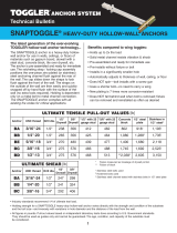
Use these
four holes
for this
installation.
1
1A
2
Toggler Bolt Installation Instructions:
a. Place mounting template on wall. The template
may have to be repositioned after next step.
Note: The bottom edge of template
must be even with fl oor. This will
help position for a range of 29” - 47”
height range).
b. Depending on which wall you are placing
the template, measure 3.88” from the wall
to the fi rst holes in template.
c. Compare level to line printed on template
to ensure mounting template is perfectly plumb.
a. Use punch to locate holes in
wall (the 4 bottom holes on
template are used for
this product).
b. Make sure that drill bit
point is centered with
cross-pattern of
hole location.
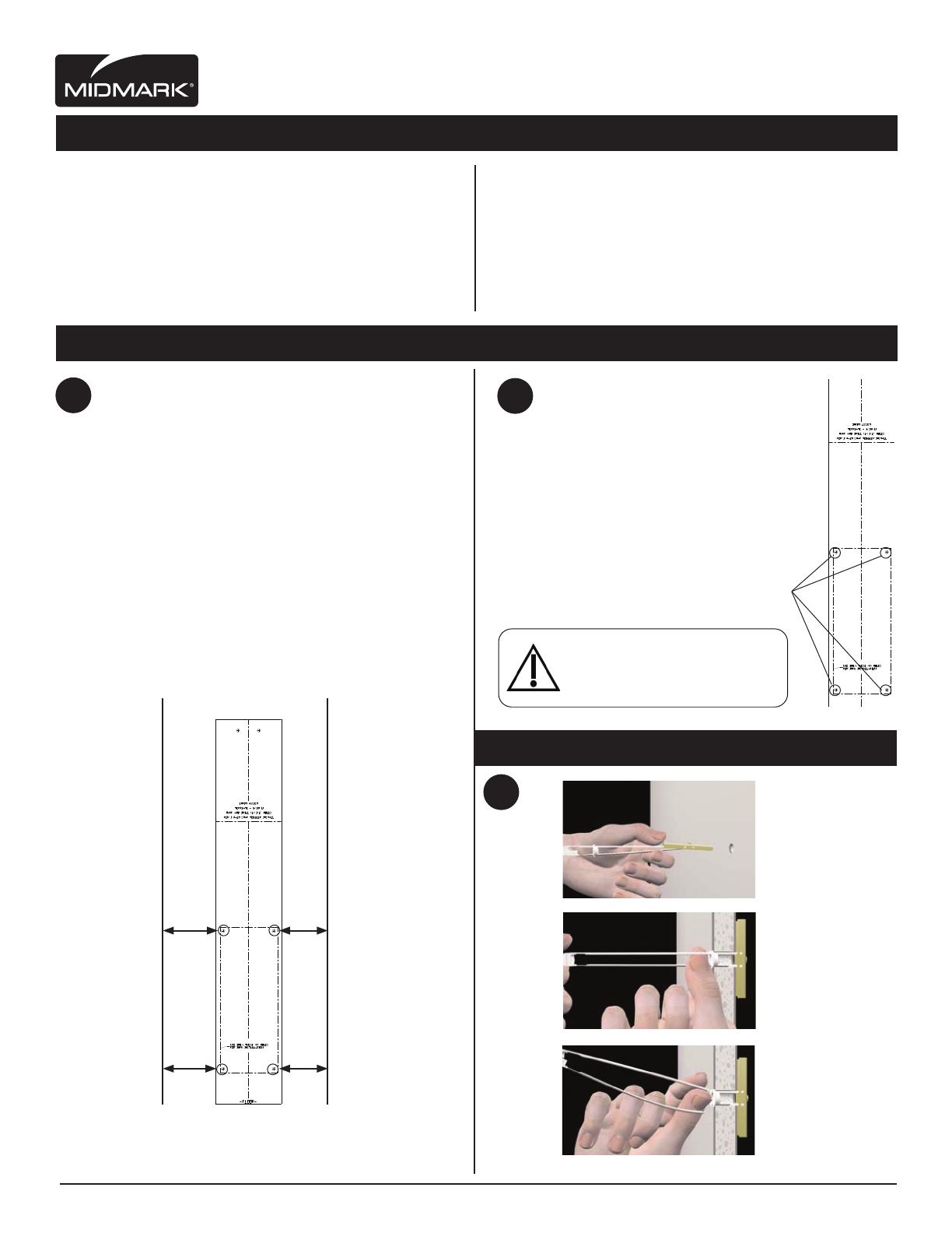
c. Install Toggler Bolts
a.
b. b.
a.
Drill 1/2” size hole.
Hold metal channel
fl at alongside plastic
straps and slide
channel through
the hole. Minimum
clearance beind wall:
only 1 7/8”
(1/2” Hole)
Hold ends of straps
together between
thumb & forefi nger
and pull toward you
until channel rests
behind wall. Rachet
cap along straps
with other hand until
fl ange of cap is
fl ush with wall.
b.
c.
Place thumb between
straps at wall. Push
thumb side to side,
snapping off straps
level with fl ange
of cap.
Right-handed
Application:
Measure 3.88”
from wall
Left-handed
Application:
Measure 3.88”
from wall
WALLWALL
3.88” 3.88”
3.88” 3.88”
Caution
Properinstallationoftoggleboltsrequired
toprovidesecurewallmounting.Minimum
drywallthicknesstobe½”.