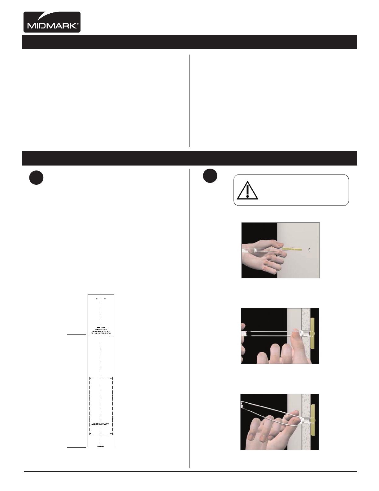
Midmark 6271 - 6276 (Wall Mounted Units) Installation guide

Category
Flat panel accessories
Type
Installation guide

Midmark 6271 - 6276 (Wall Mounted Units) offer flexible and ergonomic solutions for healthcare environments. These units allow for height adjustment of monitors, keyboards, and other accessories, promoting proper posture and reducing strain. With sturdy construction and secure mounting options, these wall-mounted units provide a stable and reliable platform for medical equipment. Whether you need to create a mobile workstation or enhance patient engagement, Midmark 6271 - 6276 units offer versatile configurations to meet your specific needs.

Midmark 6271 - 6276 (Wall Mounted Units) offer flexible and ergonomic solutions for healthcare environments. These units allow for height adjustment of monitors, keyboards, and other accessories, promoting proper posture and reducing strain. With sturdy construction and secure mounting options, these wall-mounted units provide a stable and reliable platform for medical equipment. Whether you need to create a mobile workstation or enhance patient engagement, Midmark 6271 - 6276 units offer versatile configurations to meet your specific needs.

Attention!
For OSHPD Regulated Installations, please go to
www.midmark.com to download the appropriate
OSHPD Approval and Installation documents.
6271-001 Installation Instructions
INS-6271-001 (Rev. E)
a.
Drill 1/2” size hole. Hold metal channel
at alongside plastic straps and slide
channel through the hole. Minimum
clearance beind wall: only 1 7/8”
(1/2” Hole)
Tools required:
Electric Drill with driver extension
Phillips head screwdriver/bit
1/2” Drill Bit
Punch
Stud Finder (optional)
Parts Included:
(1) Height Adjustable Column Assembly
(1) Monitor Track Assembly
(1) Keyboard Pivot Housing Assembly
(1) Keyboard Platform Assembly
(1) Track Guide Assembly
(1) Flip-up Shelf Assembly
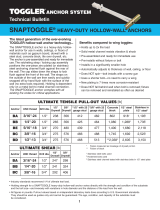
(1) Mounting Template
(8) Hilti Snaptoggle Heavy-Duty Toggle Bolts (2 extra)
(2) 1/4-20 x 2” Long Phillips Drive Pan Head Machine Screws
(4) 1/4-20 x 3” Long Phillips Drive Pan Head Machine Screws
(2) #10-24 x 1 1/4” Pan Head Phillips Drive Screws
(4) 1/4” Flat Washers
(4) 1/4-20 x 1 1/4” Long Phillips Drive Pan Head Machine Screws
(4) 10-24 x 1/2” Long Phillips Drive Flat Head Machine Screws
(4) M4-0.7 x 10mm Long Phillips Drive Flat Head Machine Screws
(4) M4-0.7 x 16mm Long Phillips Drive Flat Head Machine Screws
(4) #8-32 x 1/4” Long Phillips Drive Flat Head Machine Screws
(1) Cable Management Cover
(1) TechFlex Cable Management Sleeve
(8) Dual Lock Velcro Squares
(3) 1/16” Thick Shims
(1) Mouse House
6271-001 Installation Instructions
INS-6271-001 (Rev. E)
Installation Hardware
2
1
Toggler Bolt Installation Instructions:Toggler Bolt Installation Preparation:
a. Place mounting template on wall (See FIG.A).
Note: Place bottom line of template
on fl oor. This will position Input for a
working range of 29” - 47” height range.
b. Compare level to line printed on template
to ensure mounting template is perfectly level
(See FIG. B).
c. Use punch to locate holes in wall as
marked on template.
FIG. A
FIG. B
b.
Hold ends of straps together between thumb
& forefi nger and pull toward you until channel
rests behind wall. Rachet cap along straps
with other hand until fl ange of cap is
ush with wall.
c.
Place thumb between straps at wall. Push
thumb side to side, snapping off straps level
with fl ange of cap.
Midmark Corporation | 60 Vista Drive | PO Box 286 | Versailles, Ohio 45380-0286 | USA | midmark.com
Caution
Properinstallationoftoggleboltsrequired
toprovidesecurewallmounting.Minimum
drywallthicknesstobe½”.
6271-001 Installation Instructions
INS-6271-001 (Rev. E)
3
Mounting Height Adjustable Column Assembly & Track Guide to Wall:
Product Assembly (Monitor Track Assembly):
a. Slide Monitor Track Assembly into track guide
then into height adjustable column assembly
(See Fig. A).
b. Attach and fasten rear (2) #10 x 1 1/4” Pan
Head Phillips Drive Screws (See FIG. B).
4
FIG. A
FIG. B
Track Guide
Monitor Track
Assembly
Monitor Mount
Assembly
Height
Adjustment
Column
Assembly
Midmark Corporation | 60 Vista Drive | PO Box 286 | Versailles, Ohio 45380-0286 | USA | midmark.com
a. Align mounting holes with toggler bolts
in wall. Secure with (4) 1/4-20 x 3”
toggler fasteners (See FIG A.). NOTE:
SECURE BOTTOM TWO FASTENERS FIRST
(See Fig. B)
b. Unfasten security strap.
WARNING: COULD EXPAND RAPIDLY!
c. Depress lever and adjust height adjustment
column assembly up to the highest
position (See FIG. C).
d. Align top (2) holes in track guide with
previously installed toggler fasteners.
Secure track guide with (2) 1/4-20 x 2”
Long phillips drive pan head machine screws
(See FIG. D).
FIG. A
FIG. B
FIG. C
FIG. D
Prior to installing the
Height Adjustable Column
Assembly to wall, attach
column mounted accessory
(If applicable)!
Track Guide
Height
Adjustment
Column
Assembly
6271-001 Installation Instructions
INS-6271-001 (Rev. E)
Straight and Level Wall Wall-Mount Track Guide Shimming
a. A NOT level/straight wall may effect the
height adjustment performance of the wall
mounted workstation. If wall-mounted
workstation is rubbing against wall, proceed
to Step 6 for shim installation.
a. Adjust Height Adjustment Column Assembly to
its highest postion (See FIG. A).
a. Loosen Track Guide by loosening (Not
Removing) the (2) 1/4-20 x 2” Long Phillips
Drive Pan Head Machine Screws (See FIG. B).
b. Insert (upto 3) shims in between wall and
Track Guide. Slide Down onto loosened screws
(See FIG. C).
c. Tighten screws on Track Guide.
5
6
CONVEX WALL
SHIMS SHIMS
Upper
Half of
Product
CONCAVE WALL
LEVEL &
STRAIGHT WALL
LEVEL &
STRAIGHT WALL
Track Guide
Shim
Track Guide Track Guide
Monitor
Mount
Assembly
Height
Adjustment
Column
Assembly
FIG. B
FIG. A
FIG. C
Midmark Corporation | 60 Vista Drive | PO Box 286 | Versailles, Ohio 45380-0286 | USA | midmark.com
6271-001 Installation Instructions
INS-6271-001 (Rev. E)
8
Product Assembly (Keyboard Platform):
a. To attach the Keyboard Platform Assembly to
the Keyboard Pivot Housing Assembly, slide
out guide plate from keyboard platform.
b. Attach Keyboard Platform Assembly to
Keyboard Pivot Housing Assembly by
securing with (4) #10-24 x 1/2” Long
Phillips Drive Flat Head Machine Screws.
a. Position Keyboard Pivot Housing Assembly
onto height adjustable column assembly
(FIG. A).
Attach and fasten (4) 1/4-20 x 1 1/4” Long
Phillips Drive Pan Head Machine Screws
and (4) 1/4” Washers (FIG. B).
7
FIG. B
FIG. A
Product Assembly (Keyboard Pivot Housing:
Keyboard
Pivot
Housing
Keyboard
Platform
Assembly
Midmark Corporation | 60 Vista Drive | PO Box 286 | Versailles, Ohio 45380-0286 | USA | midmark.com
6271-001 Installation Instructions
INS-6271-001 (Rev. E)
10
Attach Monitor to Bracket:
a. Align VESA mounting hole pattern on
monitor with mounting pattern on
Monitor Bracket (See FIG. A).
b. Attach Monitor Bracket to Monitor.
Secure with either (4) M4-0.7 x 10mm or
(4) M4-0.7 x 16mm Long Phillips Drive
Flat Head Machine Screws (See FIG.B)
.
c. Attach monitor with Monitor Bracket to
Monitor Security Bracket Assembly.
Note: Monitor Bracket has a top slot which
the Monitor Security Bracket Assembly fi ts
into (See FIG. C).
d. Secure brackets with two (2) #10-24 x 1/2”
Long Phillips Drive Pan Head Machine
Screws (See FIG D).
9
FIG. C
FIG. A
FIG. B
FIG. D
FIG. B
FIG. A
Monitor
Bracket
Monitor Security
Bracket Assembly
FIG. C
FIG. D
FIG. E
Upper Cable Management:
Midmark Corporation | 60 Vista Drive | PO Box 286 | Versailles, Ohio 45380-0286 | USA | midmark.com
Upper Cable Management: For CPU’s, monitors:
For Monitor cables: Remove Cable Management
Cover (See FIG. A). Place in channel and zip-tie cables
at the top by monitor (See FIG. B).
Cable clips are to be used for keyboard and mouse
cables only (See Fig. B).
Continue to run cables behind keyboard
pivot housing (See FIG. C).
Reinstall cable mangement cover when fi nished
(See FIG. A).
For Upper CPU’s: Cables can be run arround the
cable management insert (See FIG. D). Additional
cables running out of upper cpu holder, can be
run down behind Height Adjustable Monitor
Bracket (See FIG. E).
a. Attach (8) Velcro squares together. Peel
off fi lm from one side and adhere
(4) Velcro Squares to the underside
of keyboard.
b Peel off fi lm from the other side squares
and attached to keyboard platform
(See FIG. B).
a. To attach Flip-up Shelf to bracket, ip down
bracket and place shelf onto bracket
(See FIG A).
b. Insert and tighten (4) #8-32 x 1/4” Long
Phillips Drive Flat Head Machine Screws
into top of shelf (See FIG B).
14
There are three different suggested mounting
positions for the Mouse House, they are
as follows:
a. Behind the monitor (See FIG A).
b. On the wall (make sure to check this when
assembly is adjusted to its highest position)
(See FIG. B).
c. Underneath small worksurface (See FIG. C).
Flip-up Shelf Attachment:
Mouse House Attachment:
Keyboard Attachment:
12
13
6271-001 Installation Instructions
INS-6271-001 (Rev. E)
11
Lower Cable Management: For CPU’s,
keyboard and mouse:
Run the tech-fl ex covered cables through the
back of the height adjustable column assembly
(See FIG. A).
Lower Cable Management:
FIG. A
FIG. B
FIG. A
FIG. B
FIG. C
FIG. A
FIG. B
Midmark Corporation | 60 Vista Drive | PO Box 286 | Versailles, Ohio 45380-0286 | USA | midmark.com
  • Page 1 1
  • Page 2 2
  • Page 3 3
  • Page 4 4
  • Page 5 5
  • Page 6 6
  • Page 7 7

Midmark 6271 - 6276 (Wall Mounted Units) Installation guide

Category
Flat panel accessories
Type
Installation guide

Midmark 6271 - 6276 (Wall Mounted Units) offer flexible and ergonomic solutions for healthcare environments. These units allow for height adjustment of monitors, keyboards, and other accessories, promoting proper posture and reducing strain. With sturdy construction and secure mounting options, these wall-mounted units provide a stable and reliable platform for medical equipment. Whether you need to create a mobile workstation or enhance patient engagement, Midmark 6271 - 6276 units offer versatile configurations to meet your specific needs.

Ask a question and I''ll find the answer in the document

Finding information in a document is now easier with AI