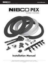
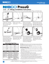
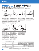
NPC280

NIBCO NPC280, CPC611HD34 User manual

  • Hello! I've reviewed the NIBCO Press System Installation Instructions and I'm ready to assist you. This document provides comprehensive guidance on how to properly install and test the NIBCO Press System to ensure a secure and leak-free connection. It details procedures for preparing copper tubing, using authorized tools, crimping fittings and valves and testing the system with air or water. Feel free to ask any questions you have about this document or specific step in the installation process.
  • What type of tubing can be used?
    Can I use any pressing tool?
    What is the maximum pressure for water leak testing?
    What is the maximum pressure for air leak testing?
Visit our website for the most current information.
78
NIBCO INC. WORLD HEADQUARTERS • 1516 MIDDLEBURY ST. • ELKHART, IN 46516-4740 • USA • PH: 1.800.234.0227
TECH SERVICES PH: 1.888.446.4226 • FAX: 1.888.336.4226 • INTERNATIONAL OFFICE PH: +1.574.295.3327 • FAX: +1.574.295.3455
www.nibco.com
www.nibco.com
AHEAD OF THE FLOW®
Installation Instructions
Visit our website for the most current information.
79
NIBCO INC. WORLD HEADQUARTERS • 1516 MIDDLEBURY ST. • ELKHART, IN 46516-4740 • USA • PH: 1.800.234.0227
TECH SERVICES PH: 1.888.446.4226 • FAX: 1.888.336.4226 • INTERNATIONAL OFFICE PH: +1.574.295.3327 • FAX: +1.574.295.3455
www.nibco.com
www.nibco.com
AHEAD OF THE FLOW
®
NIBCO Press System
The NIBCO Press System, when used with tested and authorized press-
ing tools and jaws, is designed to mechanically crimp fittings and valves
onto copper tubing to create a watertight, permanent seal. When the
switch on the pressing tool is depressed a small hydraulic pump gen-
erates thousands of pounds of crimping force to install the specially
designed fittings and valves.
System Components
Fittings and Valves
NIBCO Press System copper or bronze fittings and valves
Tubing
ASTM B 88 seamless Hard Drawn Copper Water Tube: Types K, L and M as
well as 1/2", 3/4" and 1" annealed copper tubing.
Pressing Tools, Chains and Jaws
The pressing tool, chain and jaw are important parts of ensuring a reliable,
permanent connection between NIBCO Press System fittings and valves and
the copper water tube.
CAUTION — Use only pressing tools and jaw sets that have been tested
and authorized for use with NIBCO Press System fittings and valves (1). Use
of unauthorized pressing tools and/or jaws may result in an improper seal
that could cause extensive property damage.
Pressing Tool Safety
Only use authorized pressing tools and jaws with NIBCO Press System
fittings and valves. Other uses or modification of the jaws for other
applications may damage the press tool, damage the jaws and/or cause
personal injury.
Keep fingers and hands away from jaws during pressing cycle. Your
fingers or hands can be crushed, fractured or amputated if they become
caught between the jaw tips or between the jaw and any other object.
Always wear safety glasses while using pressing tools and jaws.
• Never attempt to repair a damaged jaw set. A jaw that has been
modified in any manner can fail during crimping resulting in serious
injury. Discard the entire damaged jaw set. Replace with a new jaw set.
WARNING: Please read these installation instructions and the manu-
facturer's pressing tool and jaw operators manual(s) carefully prior to
installation of the NIBCO Press System. Failure to understand and follow
the contents of this manual may result in extensive property damage,
severe personal injury or death.
Please contact NIBCO Technical Services at 888.446.4226 if you have instal-
lation questions.
NIBCO® Press System — Installation Instructions
(1) See approved tool and jaw compatibility matrix in this catalog.
Revised 9/17/2019
Chemical Compatibility
Please consult the most current edition of the NIBCO Chem-Guide for recommendations regarding chemical compatibility of material exposure to specic
media and media-treatment additives. The NIBCO Chem-Guide is a general guide on the topic of chemical compatibility and is by no means an exhaustive
resource on the subject. Ultimately, proper material selection is the responsibility of the installer and/or end-user, taking into account all aspects of a system’s
design and intended use.
Galvanic Potential in Piping Systems
Galvanic corrosion or dissimilar metal corrosion is an electrochemical process that is created through the electrical interaction of two different metals under the
inuence of a conductive media (i.e. an electrolyte). An electrolytic cell, much like a battery, is generated by these dissimilar metals using water as the electrolyte.
The electrical charge, developed within the electrolytic cell, drives a preferential attack on the more electrically active metal with the water acting as the recipient
of the discarded metal ions. Such galvanic attack is often encountered in service where iron or steel components are installed, and later corrode, in a largely
copper piping system. Please consult NIBCO Technical Bulletin NTB-0714-01 Dielectric Products Relative to Electrolysis and Galvanic Corrosion.
Visit our website for the most current information.
80
NIBCO INC. WORLD HEADQUARTERS • 1516 MIDDLEBURY ST. • ELKHART, IN 46516-4740 • USA • PH: 1.800.234.0227
TECH SERVICES PH: 1.888.446.4226 • FAX: 1.888.336.4226 • INTERNATIONAL OFFICE PH: +1.574.295.3327 • FAX: +1.574.295.3455
www.nibco.com
www.nibco.com
AHEAD OF THE FLOW®
Installation Instructions for 1/2" - 2"
Press Fittings and Valves
WARNING: To prevent serious injury, inspect the pressing tool, battery
charger (if applicable) and jaw sets according to the procedure outlined in the
pressing tool instruction manual prior to beginning installation.
Failure to clean jaws can result in an improper connection that can lead to
extensive property damage.
Preparing the Copper Tube
1. Select clean, undamaged copper tube and cut to desired length. Cut tube
end square using a tube cutter or fine-toothed saw. Do not crimp over
damaged, scratched, gouged, or otherwise damaged tubing ends. Do not
crimp over etch print streams on tubing. (Figure 1).
Figure 1 — Cut tube to desired length
2. Deburr the tube inside and outside diameter using a half-round file or a
deburring tool.
3. Clean the tube end of all dirt, oil and grease. (Emery cloth or sandpaper
to clean the tube or remove oxidation should not be used.)
Inserting the Tube into the Fitting or Valve
1. Check the fitting to make sure the EPDM seal is in place, clean and free of
dirt and debris (Figure 2).
Figure 2 — Check for EPDM Seal
WARNING: Never lubricate the EPDM seal in the NIBCO Press System fit-
ting or valve with anything other than water. Oil-based lubricant, dirt or debris
may damage the seal. An improper seal can lead to extensive property damage.
Figure 3 — Marking for Insertion Depth
2. Mark the tube with a permanent marker to indicate the proper tube
insertion depth (Figure 3).
3. Refer to the minimum insertion depth table for correct depths
4. Insert the tube into the fitting or valve using a twisting motion. Make sure
that the tube is fully inserted into the fitting stop or shoulder.
CAUTION: Tubing that is difficult to insert may have burrs or could be
out-of-round. Burrs must be removed and tubing end must be undamaged.
Make sure tube is inserted to the proper depth. Failure to do so may result
in an improper seal.
Attaching Pressing Jaws
1. Make sure the battery is removed or the cord is unplugged on the pressing
tool prior to attaching or changing the crimp jaws.
2. Push and twist to open the jaw set mounting pin. (Figure 4).
Figure 4 — Pushing and twisting to open the jaw set mounting pin
3. If press tool contains a jaw set, slide it out of the crimping tool.
NIBCO® Press System — Installation Instructions
Tube Size
Inches Inches mm
1/2 11/16 18
3/4 7/8 22
1 7/8 22
1141 25
11213835
2 11238
Insertion Depth (min.)
Revised 11/9/2017
Visit our website for the most current information.
81
NIBCO INC. WORLD HEADQUARTERS • 1516 MIDDLEBURY ST. • ELKHART, IN 46516-4740 • USA • PH: 1.800.234.0227
TECH SERVICES PH: 1.888.446.4226 • FAX: 1.888.336.4226 • INTERNATIONAL OFFICE PH: +1.574.295.3327 • FAX: +1.574.295.3455
www.nibco.com
www.nibco.com
AHEAD OF THE FLOW
®
4. Select the jaw set that corresponds to the size of the joint to be crimped
and insert the jaw set into the pressing tool (Figure 5).
Figure 5 — Inserting the NIBCO Press System jaw
5. Push the jaw set mounting pin until it clicks into position.
NOTE: The tool will not properly press unless the pin is fully engaged.
Crimping a NIBCO Press System Fitting or Valve
1. Make sure the tubing is inserted to the proper depth in the fitting.
(Figure 6).
Figure 6 — Inserting the tube to proper depth
2. Squeeze jaw arms to open the jaw set.
3. Place the open jaws around the fitting and ensure that the contour of the
jaw is properly aligned with the contour of the fitting (Figure 7).
Figure 7 — Open the jaw set and place around the fitting
4. Make sure the tool is perpendicular to the tubing and depress the switch
(Figure 8). Keep the trigger depressed from the time the cycle begins and
the rollers contact the jaw arms until the end of the entire crimp cycle.
Figure 8 — Jaw set should be square to tubing
5. Once the crimp is complete, press the jaw arms to open the jaw and
remove from the fitting.
If the tool displays an LED flash or emits an audible alarm, please refer to
the tool instruction manual for troubleshooting suggestions.
CAUTION Avoid handling sharp edges that may have formed on the fitting
during the crimping operation.
Inspecting the Crimp
1. Inspect the crimped fitting to ensure proper crimp.
NOTE: The use of the NIBCO Press System jaw will produce a unique witness mark “N”
on the crimped fitting.
2. Inspect the crimped fitting checking the connection for the following
problems:
Not fully inserted tube, double check depth marks
Incorrect jaw alignment with the fitting contour
If any problems are found, a new section of tubing and a new fitting will
need to be prepared, installed and crimped.
3. Test the NIBCO Press System in accordance with crimp intergrity testing
instructions for fittings and valves in this catalog.
NIBCO® Press System — Installation Instructions
Revised 11/9/2017
Visit our website for the most current information.
82
NIBCO INC. WORLD HEADQUARTERS • 1516 MIDDLEBURY ST. • ELKHART, IN 46516-4740 • USA • PH: 1.800.234.0227
TECH SERVICES PH: 1.888.446.4226 • FAX: 1.888.336.4226 • INTERNATIONAL OFFICE PH: +1.574.295.3327 • FAX: +1.574.295.3455
www.nibco.com
www.nibco.com
AHEAD OF THE FLOW®
NIBCO® Press System — Installation Instructions
Installation Instructions for 2 1/2" - 4"
Press Fittings and Valves
WARNING: To prevent serious injury, the pressing tool, battery charger
(if applicable) and pressing chains should be inspected according to the
procedure outlined in the pressing tool instruction manual prior to beginning
installation.
Failure to clean pressing chains can result in an improper connection that can
lead to extensive property damage.
Preparing the Copper Tube
1. Select clean, undamaged copper tube and cut to the desired length. Cut tube
end square using a tube cutter or ne-toothed saw. Do not crimp over dam-
aged, scratched, gouged, or otherwise damaged tubing. Do not crimp over
etch print streams on tubing (Figure 1).
2. Deburr the tube inside diameter using a half-round le or deburring tool.
Remove any copper shavings or lings (Figures 2 & 3).
Figure 1: Cut tube to desired length using s tube cutter
3. Deburr the tube outside diameter using a half-round le to prevent damage to
the EPDM seal (Figure 4).
Figure 4: Deburr outside diameter using a half-round file
4. Clean the tube end of all contamination, oils and shavings. A smooth transition
chamfer is recommended to ease tube insertion past the seal. (Emery cloth or
sandpaper to clean the tube or remove oxidation should not be used.)
Inserting the Tube into the Fitting or Valve
1. Check the tting to make sure that the seal is in place and is free of oil or
grease. Only original NIBCO® EPDM seals are to be used when making a
press connection with NIBCO Press System ttings and valves. If it is neces-
sary to lubricate the seals, use water only. DO NOT use any petroleum-based
lubricants (Figure 5).
Figure 5: Check for EPDM seal
WARNING: Never lubricate the EPDM seal in a NIBCO Press System fitting
or valve with anything other than water. Oil-based lubricants, dirt or debris may
damage the seal. An improper seal can lead to extensive property damage.
2. Mark the proper insertion depth on the tube with a permanent marker prior to
insertion, based on insertion depth chart. Refer to minimum insertion depth
table for correct depths.
3. Insert the tube into the fitting or valve using a twisting motion. Make sure
that the tube is fullly inserted into the fitting or valve.
WARNING: If tube is not inserted to the proper depth, an inadequate seal
may result.
CAUTION: Tubing that is difficult to insert may have burrs or could be
out-of-round. Burrs must be removed and tubing end should be undamaged.
Make sure tube is inserted to the proper depth. Failure to do so may result in
an improper seal.
NIBCO® Press System
Insertion Depth Chart
Tube Size 21/2” 3” 4”
Insertion Depth (min.) 11/2” 15/8” 21/8
Figure 2: Deburr inside diameter using a half-round file
Figure 3: Deburr inside diameter deburring tool
Revised 11/9/2017
Visit our website for the most current information.
83
NIBCO INC. WORLD HEADQUARTERS • 1516 MIDDLEBURY ST. • ELKHART, IN 46516-4740 • USA • PH: 1.800.234.0227
TECH SERVICES PH: 1.888.446.4226 • FAX: 1.888.336.4226 • INTERNATIONAL OFFICE PH: +1.574.295.3327 • FAX: +1.574.295.3455
www.nibco.com
www.nibco.com
AHEAD OF THE FLOW
®
Crimping a NIBCO Press System Fitting or Valve
1. Make sure that the battery is removed or that the cord is unplugged on the
pressing tool prior to attaching or changing the adapter jaw.
2. Select the correct size pressing chain. Pull the pin on the chain which allows
the segments to open. Position the chain on the raised bead and wrap the chain
around the tting with the "pipe side" designation facing the tube. When the
chain is fully wrapped around the tting, reinsert the pin to secure the chain
on the assembled joint. Visually inspect the mark made for insertion depth, to
ensure the tube remained in position (Figure 6).
Figure 6: Placement of the pressing chain onto fitting or valve
3. Release the pin (push and twist) on the jaw holder of the pressing tool, and
install the adapter jaw on the tool. Return the pin to its original position, secur-
ing the jaw. The red sleeve on the tool must be in the back position to allow for
crimping sizes 2½”, 3 and 4” (Figure 7).
Figure 7: Placement of adapter jaw into the tool
4. Squeeze adapter jaw arms to open the jaw. Rollers must be fully retracted
to open the adapter jaw. Place the open adapter jaw into the grooves in the
pressing chain and let go of the jaw arms (Figure 8).
Figure 8: Placement of adapter jaw into pressing chain
5. Make sure the tubing is inserted to the proper depth in the tting or valve, and
that the tube and tting or valve are aligned properly.
6. With the pressing tool perpendicular to the tube, begin the pressing cycle by
pulling the trigger of the pressing tool.
7. Keep the trigger depressed from the time the cycle begins and the rollers con-
tact the jaw arms until the end of the entire cycle. Remove the pressing tool
and adapter jaw from the pressing chain. Remove the pressing chain from the
tting.
If the tool displays an LED ash or emits an audible alarm, please refer to the
toolinstruction manual for troubleshooting suggestions.
CAUTION: Avoid sharp edges that may have formed on the fitting during
the crimping operation.
Inspecting the Crimp
1. Inspect the crimped fitting or valve to ensure proper crimp. The final crimp
should appear pressed uniformly around the fitting or valve (Figure 9).
Figure 9: Inspection of final crimp
NOTE: The use of the NIBCO Press System chain will produce a unique witness mark “N”.
2. Inspect the crimped tting checking the connection for the following problems:
Not fully inserted tube, double check depth marks
Incorrect chain alignment with the tting contour
If any problems are found, a new section of tubing and a new tting will need
to be prepared, installed, and crimped.
3. Test the NIBCO Press System in accordance with crimp integrity testing instruc-
tions for ttings and valves in this catalog.
NIBCO® Press System — Installation Instructions
Revised 11/9/2017
CAUTION:
NIBCO press fittings and valves
(2½”, 3”, 4” ends) to be installed ONLY
with:
• NIBCO PC-100 and PC-280 pressing tools
• NIBCO PC-5 adapter jaw
• NIBCO pressing chain - 2½” (PC-2),
3” (PC-3), 4” (PC-4)
Visit our website for the most current information.
84
NIBCO INC. WORLD HEADQUARTERS • 1516 MIDDLEBURY ST. • ELKHART, IN 46516-4740 • USA • PH: 1.800.234.0227
TECH SERVICES PH: 1.888.446.4226 • FAX: 1.888.336.4226 • INTERNATIONAL OFFICE PH: +1.574.295.3327 • FAX: +1.574.295.3455
www.nibco.com
www.nibco.com
AHEAD OF THE FLOW®
PRESSURE TESTING:
NIBCO recommends the following leak testing procedures when installing NIBCO Press System with the leak detection feature. These test procedures allow
the installer to find un-pressed connections while the system is being tested under pressure.The uniquely designed EPDM o-ring allows fluids or gases to flow
past the seal and leak when the fitting has not yet been pressed. When the fitting has been pressed, the o-ring will create a water tight seal around the tube.
AIR LEAK TESTING:
1. Pressurize system up to 15 psi maximum using dry, oil free compressed air, carbon dioxide, or nitrogen.
2. Allow system pressure to stabilize for a minimum of 2 hours.
3. If system pressure has dropped, add more air to bring entire system up to 15 psi maximum. If system pressure increases above 15 psi, bleed off excess
pressure to ensure system is at a maximum pressure of 15 psi.
4. If the system pressure continues to drop, inspect all joints for un-pressed fittings. The NIBCO Press System press fittings with the leak detection feature
are designed to leak in an un-pressed condition.
5. Check all press joints for air leaks using a commercially available leak test solution or a soap and water mixture. Do not use a soap that contains Mineral
Spirits or a Hydrocarbon/ petroleum that might attack the EPDM O-rings.
6. Once the system has been confirmed to be leak free, pressure can be increased to the recommended working pressure to verify system integrity.
WATER LEAK TESTING:
1. Pressurize system up to 50 psi maximum using potable water.
2. Allow system pressure to stabilize for a minimum of 2 hours.
3. If system pressure has dropped, add more water to bring entire system up to 50 psi maximum. If system pressure increases above 50 psi, bleed off
excess pressure to ensure system is at a maximum pressure of 50 psi.
4. If the system pressure continues to drop, inspect all joints for un-pressed fittings. The NIBCO Press System press fittings with the leak detection feature are
designed to leak in an un-pressed condition.
5. Check all press joints for leaking water.
6. Once the system has been confirmed to be leak free, water pressure can be increased to the recommended working pressure to verify system integrity.
SYSTEM INTEGRITY TESTING*:
Once a system has been confirmed to be properly installed and no press connections have been left uncrimped, the system is recommended for
testing up to the maximum non-shock working pressure of 200 psi hydrostatic.
NOTE: While NIBCO Press System products are tested to pressures as high as 600 psi, the product system rating limitation of 200 psi is in place to ensure a safety
factor of three-times proof-testing according to ASME B16.51 Copper and Copper Alloy Press-Connect Pressure Fittings.
SYSTEM INTEGRITY TESTING AT HIGHER PRESSURES*:
NIBCO Press System products can be tested at hydrostatic pressures higher than 200 CWP, not exceeding a maximum pressure of 300 psi hydrostatic for a
maximum test duration of 24 hours, when assembled and tested according to the methods prescribed above.
CAUTION: These testing parameters and protocols apply only to NIBCO products as detailed above: NIBCO accepts no responsibility or liability for any other
manufacturer’s products that may be damaged as a result of such testing.
*System integrity testing applies to leak detect and non-leak detect fittings and valves.
NIBCO® Press System — Crimp Integrity Testing
Instructions for Fittings & Valves
Revised 2/28/2020
Visit our website for the most current information.
85
NIBCO INC. WORLD HEADQUARTERS • 1516 MIDDLEBURY ST. • ELKHART, IN 46516-4740 • USA • PH: 1.800.234.0227
TECH SERVICES PH: 1.888.446.4226 • FAX: 1.888.336.4226 • INTERNATIONAL OFFICE PH: +1.574.295.3327 • FAX: +1.574.295.3455
www.nibco.com
www.nibco.com
AHEAD OF THE FLOW
®
Minimum Distance Between Joints
To prevent distortion of the tubing, certain fitting sizes require a minimum
distance between crimp joints (refer to Chart 1 below). Failure to provide this
minimum distance may result in an improper seal.
Spacing
1. Sufficient clearance must be left around each joint to allow room for the
pressing tool and jaw to be attached without interference.
Clearance Requirements — Standard Jaw Sets
NIBCO® Press System — Installation Instructions
Tube Dia. Inches mm Inches mm
1/2 15/16 24 15/8 41
3/4 7/8 22 21/8 54
1 11/4 31 21/2 64
11/4 11/8 29 27/8 73
11/2 2 51 43/8 111
2 2 51 43/8 111
A (min.) B (min.)
Tube Dia. Inches mm Inches mm Inches mm
1/2 11/8 28 13/8 35 21/2 64
3/4 1 26 11/2 38 21/2 64
1 15/16 34 13/4 45 3 76
11/4 11/4 32 21/4 57 31/8 80
11/2 21/8 54 31/8 80 5 127
2 21/8 54 31/8 80 5 127
21/2 35/8 92 37/8 98 53/8 137
3 37/8 98 43/4 120 67/8 175
4 5 127 51/2 140 77/8 200
A (min.) B (min.) C (min.)
System Support
CAUTION — In any installation, the system should be suported to ensure
the minimum stress is imposed on the tube and joints. The NIBCO Press
System should be supported in accordance with normal practice and to local
jurisdiction piping code.
Softening of Copper Tubing
A NIBCO Press System installation should not be conducted within 12" of a
brazed joint. The high temperature required for capillary joinery may cause
the copper tube to become annealed and render it too soft for proper crimp-
ing. However, a NIBCO Press System product may be crimped adjacent to a
soldered joint, as normal temperatures created by silver soldering are not
hot enough to cause the copper tube to become annealed.
CAUTION — Brazing or soldering should not be conducted within 12" of
an existing NIBCO Press System connection as this may damage the EPDM
seal. If there is any concern about heat damage to the O-ring, a cold, wet
cloth should be wrapped around the crimped connection prior to soldering
or brazing.
Tool perpendicular to wall
Tool angled to wall
NOTE: Clearance dimensions for 21/2", 3" & 4" are for wrapping pressing
chains around fittings.
A (min.)
Tube Dia. Inches mm
12"* 0 0
34"* 0 0
1"* 0 0
114"* 0 0
112"* 0 0
2"* 0 0
212" 38" 10
3" 38" 10
4" 38" 10
*No minimum distance required.
Revised 9/15/2021
/