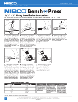
NIBCO Bench Press GYM Fitting Operating instructions

Type
Operating instructions

NIBCO Bench Press GYM Fitting: Experience efficient and reliable connections for your fuel and gas lines. Designed for use in mechanical applications, these carbon steel fittings provide a secure and leak-proof seal for a wide range of media, including fuel oil, LP gas, natural gas, and more. With operating pressures ranging from 125 to 200 psi and temperatures from -40°F to 180°F, these versatile fittings are suitable for various industrial and commercial applications.

NIBCO Bench Press GYM Fitting: Experience efficient and reliable connections for your fuel and gas lines. Designed for use in mechanical applications, these carbon steel fittings provide a secure and leak-proof seal for a wide range of media, including fuel oil, LP gas, natural gas, and more. With operating pressures ranging from 125 to 200 psi and temperatures from -40°F to 180°F, these versatile fittings are suitable for various industrial and commercial applications.

NIBCO INC. WORLD HEADQUARTERS • 1516 MIDDLEBURY ST. • ELKHART, IN 46516-4740 • USA • PH: 1.800.234.0227
TECH SERVICES PH: 1.888.446.4226 • FAX: 1.888.336.4226 • INTERNATIONAL OFFICE PH: +1.574.295.3327 • FAX: +1.574.295.3455
www.nibco.com
Visit our website for the most current information.
BPG-FSP-1220-R010523 © 2023 NIBCO INC., All Rights Reserved.
Submittal Package
Job Name Contractor
Job Location Wholesaler
Engineer NIBCO Sales Rep
Heating Fuel Oil Liquid Propane/Butane Gas Natural Gas Diesel Fuel
Compressed Air Oxygen (non-medical) Nitrogen Carbon Dioxide
Argon Vacuum Systems
PRODUCT DESCRIPTION
NIBCO BenchPressG carbon steel fittings for use in mechanical applications. Available sizes range from ½” through 1½” in
diameter. Product is designed to join Schedule 10 to 40 steel pipe as defined by ASTM A53, A106, A135 and A795. Fittings
are approved for installations in both above and below ground applications. Per code, local inspector approval must be
obtained prior to installation below ground.
STANDARDS AND CODES
NFPA 54/Z223.1 National Fuel Gas Code
NFPA 58 Liquified Petroleum Gas Code
ASME B31 Code for Pressure Pipe
NFPA 30 Flammable and Combustible Liquids Code
NFPA 30A Code for Motor Fuel Dispensing Facilities
and Repair Garages
NFPA 31 Standard for the Installation of Oil Burning
Equipment (supply line only)
CSA ANSI LC-4/CSA 6.32
Uniform Plumbing Code (UPC)*
National Plumbing Code of Canada
International Mechanical Code
*Uniform Plumbing Code is a copyrighted publications of the International Association of Plumbing and Mechanical Officials
THIRD PARTY LISTINGS AND CERTIFICATIONS
CSA Group: Gas Accessory Devices - Press Connect Type
Metallic Fittings, Class 3305-11 (Canada Standards) and
3305-91 (US Standards)
IAPMO R&T: File #11446, Press-connect metallic fittings
for use in fuel gas distribution systems, US and Canada
OPERATING PARAMETERS
Operating Pressure: Ranges from 125 to 200 psi max
depending on the application
Air Test Pressure: 15 psi maximum
Operating Temperature: -40°F to 180°F
2
NIBCO INC. WORLD HEADQUARTERS • 1516 MIDDLEBURY ST. • ELKHART, IN 46516-4740 • USA • PH: 1.800.234.0227
TECH SERVICES PH: 1.888.446.4226 • FAX: 1.888.336.4226 • INTERNATIONAL OFFICE PH: +1.574.295.3327 • FAX: +1.574.295.3455
www.nibco.com
Visit our website for the most current information.
AHEAD OF THE FLOW®
BenchPressGTM Submittal Package
BenchPressGTM Fitting Applications Chart
Types of Service Comments Pressure Temperature
Compatible with
HNBR Seal
Oil and Lubricant
Heating Fuel Oil 125 psi -40°F to 180°F
Diesel Fuel 125 psi
Gear Grease 150 psi 104°F
Engine Oil 150 psi Ambient
Hydraulic Fluid Mineral Based 200 psi Ambient
Transmission Fluid 200 psi Ambient
Gases
Natural Gas & LP Gas 125 psi max -40°F to 180°F
Compressed Air More than 25mg/m3 Oil Content 200 psi Up to 140°F
Oxygen - (non medical) Oil and Fat Free/Non Liquid 140 psi Up to 140°F
Nitrogen 200 psi Up to 140°F
Carbon Dioxide 200 psi Up to 140°F
Argon 200 psi Up to 140°F
Vacuum Max 29.2"
of Hg Up to 140°F
BenchPressG HNBR Sealing Element
Operating Temperature: -40°F to 180°F
3
NIBCO INC. WORLD HEADQUARTERS • 1516 MIDDLEBURY ST. • ELKHART, IN 46516-4740 • USA • PH: 1.800.234.0227
TECH SERVICES PH: 1.888.446.4226 • FAX: 1.888.336.4226 • INTERNATIONAL OFFICE PH: +1.574.295.3327 • FAX: +1.574.295.3455
www.nibco.com
Visit our website for the most current information.
AHEAD OF THE FLOW
®
BenchPressGTM Submittal Package
4
NIBCO INC. WORLD HEADQUARTERS • 1516 MIDDLEBURY ST. • ELKHART, IN 46516-4740 • USA • PH: 1.800.234.0227
TECH SERVICES PH: 1.888.446.4226 • FAX: 1.888.336.4226 • INTERNATIONAL OFFICE PH: +1.574.295.3327 • FAX: +1.574.295.3455
www.nibco.com
Visit our website for the most current information.
AHEAD OF THE FLOW®
BenchPressGTM Submittal Package
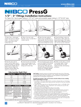
1/2” - 11/2” Fitting Installation Instructions, continued...
For ASTM A53, A106, A135, A795 (Schedule 10 to 40) carbon steel pipe in 1/2” to 1½ ” sizes
Leak Testing: Unpressed connections are located by pressurizing the system with air. When testing with compressed air, the proper
maximum pressure is 15 psi. Following a successful leak test, the system may be pressure tested up to 200 psi if required by local code
requirements or project specifi cations. Leak testing with air can be dangerous at high pressures.
The following standards, codes, and instructions should be followed when installing
NIBCO® BenchPressGTM ttings for fuel gas:
The installation of the fuel gas system shall be made in accordance with local codes, or in the absence of local codes, in accordance
with the National Fuel Gas Code NFPA 54, the LP-Gas Code NFPA 58 as applicable.
For use with ASTM A53, A106, A795 and A135 carbon steel pipe.
Undue stress or strain on the fi ttings and the tubing is to be avoided.
Concealed pipe and fi ttings shall be protected from puncture threats.
If the installation requires components in addition to those supplied by the fi tting manufacturer, those components shall be specifi ed.
The instructions shall state that only the components provided or specifi ed by the manufacturer are to be used in the installation.
The fi tting/pipe system shall not be used as a grounding electrode for an electrical system.
The inspection, testing and purging of the installation shall be performed using procedures specifi ed in Part 4 of the National Fuel Gas
Code NFPA 54, ANSI Z223.1, the LP-Gas Code NFPA 58 section 3.2-10 as applicable or in accordance with the requirements of the
applicable local codes.
For use with natural, propane, mixed, and manufactured gasses in the vapor state, not in the liquid state.
The fi tting/pipe system shall not be used as a means of support.
Notes:
1. To ensure a proper press, maintain the specifi ed minimum distance between fi ttings. The pressing jaw must have clearance to
the adjacent fi tting. Failure to maintain the minimum specifi ed distance may result in an improper seal.
2. A minimum distance to welds must always be maintained.
A minimum of 4 inches must be maintained when welding adjacent to a BenchPressG fi tting and a minimum of 3 feet must be
maintained when welding in-line. The following precautions should be used to protect the BenchPress fi tting:
Wrap the press fi tting connection with a cold wet rag
Protect the press fi tting connection with a weld blanket
Fabricate weld connections prior to installing the press fi tting
Pipe Diameter (in) Distance Between Fittings A (in)
1/2 0.20
3/4 0.20
1 0.20
1-1/4 0.59
1-1/2 0.59
A
5
NIBCO INC. WORLD HEADQUARTERS • 1516 MIDDLEBURY ST. • ELKHART, IN 46516-4740 • USA • PH: 1.800.234.0227
TECH SERVICES PH: 1.888.446.4226 • FAX: 1.888.336.4226 • INTERNATIONAL OFFICE PH: +1.574.295.3327 • FAX: +1.574.295.3455
www.nibco.com
Visit our website for the most current information.
AHEAD OF THE FLOW
®
BenchPressGTM Submittal Package
NIBCO INC. LIMITED WARRANTY
Applicable to NIBCO BenchPress & BenchPressG
NIBCO INC. warrants each NIBCO BenchPress & BenchPressG fitting and flange (together, the “NIBCO Products”) to be free from
defects in materials and workmanship under normal use, service, and maintenance in accordance with the product specifications
(including, but not limited to installation recommendations) for a period of ten (10) years from the Warranty Commencement
Date. The Warranty Commencement Date shall be the date upon which the NIBCO Products are installed.
NIBCO will repair or replace – at its option and at no charge –NIBCO Products that have been determined by NIBCO, or an
authorized representative or agent thereof, to have failed solely because of a defect in materials or workmanship under normal
use, service, and maintenance during the warranty period. Replacements shall be shipped free of charge to the owner.
This limited warranty applies to all NIBCO Products installed, tested, applied, and used in accordance with NIBCO’s approved
and published recommendations and instructions.
This warranty does not cover any failure or damage for or caused by:
1. any product, parts, or systems which are not manufactured or sold by NIBCO;
2. any NIBCO Product which is used for purposes other than a purpose authorized by NIBCO;
3. any NIBCO Product not installed, tested, applied, used, or maintained in accordance with NIBCO’s recommended instal-
lation guidelines and instructions;
4. any NIBCO Product not installed or used in accordance with applicable codes;
5. any damage caused by, contributed in whole or in part by, or resulting from, any of the following:
a. abuse, misuse, mishandling, alteration, tampering, neglect, or accidental damage such as, without limitation, van-
dalism;
b. natural disasters, such as, without limitation, flooding, windstorm, and lightning;
c. attachments or modifications not authorized by NIBCO;
d. external, physical or chemical qualities, or an unsuitable or hostile environment;
e. any defects other than those in material or workmanship; or
f. any other cause beyond the control of NIBCO.
NIBCO DISCLAIMS ANY AND ALL LIABILITY FOR ANY OTHER DIRECT OR INDIRECT, INCIDENTAL, OR CONSEQUENTIAL
DAMAGES OF ANY KIND, INCLUDING BUT NOT LIMITED TO, ECONOMIC LOSS, LOSS OF BUSINESS, LOST PROFITS,
PUNITIVE DAMAGES, MOLD INTRUSION, WATER DAMAGE, ETC.
Some states do not allow the exclusion or limitation of damages, so the above limitation or exclusion may not apply to you.
THIS WARRANTY IS THE ONLY WARRANTY FOR THE NIBCO PRODUCTS PROVIDED BY NIBCO, AND IS AND SHALL BE IN
LIEU OF ANY AND ALL OTHER WARRANTIES, EXPRESSED OR IMPLIED, INCLUDING, BUT NOT LIMITED TO, AN IMPLIED
WARRANTY OF MERCHANTABILITY OR FITNESS FOR A PARTICULAR PURPOSE, AND FOR ALL OTHER OBLIGATIONS OR
LIABILITIES ON THE PART OF A MANUFACTURER. NO EMPLOYEE OF NIBCO, OR ANY OTHER DISTRIBUTOR, AGENT, OR
OTHER PERSON OR BUSINESS, IS AUTHORIZED TO MAKE ANY OTHER WARRANTY ON BEHALF OF NIBCO.
Some states do not allow limitations on implied warranties, so the above limitation may not
apply to you.
In the event any defect occurs which is believed to be covered by this warranty, NIBCO
Technical Services must immediately be contacted by calling 888.446.4226 or emailing
CS-TechnicalSer[email protected]. NIBCO Technical Services after being contacted will make
further arrangements for the product’s return to NIBCO at the customer’s expense for review
and evaluation.
This warranty gives you specific legal rights, and you may also have other rights which vary
from state to state.
NIBCO® BenchPressTM and BenchPressGTM Limited Warranty
Revised 12/2/2021
6
NIBCO INC. WORLD HEADQUARTERS • 1516 MIDDLEBURY ST. • ELKHART, IN 46516-4740 • USA • PH: 1.800.234.0227
TECH SERVICES PH: 1.888.446.4226 • FAX: 1.888.336.4226 • INTERNATIONAL OFFICE PH: +1.574.295.3327 • FAX: +1.574.295.3455
www.nibco.com
Visit our website for the most current information.
AHEAD OF THE FLOW®
BenchPressGTM Submittal Package
ADAPTERS
PCH203
Adapter P x F – Carbon Steel
APPROX. DIM. A DIM. B
NOM. SIZE NET WT./LBS. INCHES INCHES
1/2 .234 .73 1.83
3/4 .360 .83 1.97
3/4 x 1/2 .340 .83 1.97
2 1.700 2.00 3.00
PCH217
Cap P – Carbon Steel
APPROX. DIM. A DIM. B
NOM. SIZE NET WT./LBS. INCHES INCHES
1/2 .173 .30 1.40
3/4 .258 .36 1.50
1 .370 .33 1.71
1 ¼ .559 .73 2.58
1 ½ .729 .85 2.78
2 1.030 .81 2.81
A
B
PCH204
Adapter P x M – Carbon Steel
APPROX. DIM. A DIM. B
NOM. SIZE NET WT./LBS. INCHES INCHES
1/2 .206 .98 2.09
3/4 .338 1.06 2.20
1 .460 1.14 2.52
1 ¼ .941 2.17 4.02
1 ½ 1.167 2.27 4.20
2 1.670 2.31 4.32
CAPS
A
B
B
PCH201 (No Stop)
Repair Coupling P x P –
Carbon Steel
APPROX. DIM. B
NOM. SIZE NET WT./LBS. INCHES
1/2 .260 2.81
3/4 .349 3.09
1 .544 3.36
1 ¼ .934 4.46
1 ½ 1.180 4.74
2 1.540 4.86
COUPLINGS
PCH200
Coupling P x P – Carbon Steel
APPROX. DIM. A DIM. B
NOM. SIZE NET WT./LBS. INCHES INCHES
1/2 .274 .61 2.81
3/4 .371 .80 3.09
1 .548 .61 3.36
1 ¼ .916 .76 4.46
1 ½ 1.202 .88 4.74
2 1.550 .84 4.86
A
B
A
B
Revised 1/5/2023
7
NIBCO INC. WORLD HEADQUARTERS • 1516 MIDDLEBURY ST. • ELKHART, IN 46516-4740 • USA • PH: 1.800.234.0227
TECH SERVICES PH: 1.888.446.4226 • FAX: 1.888.336.4226 • INTERNATIONAL OFFICE PH: +1.574.295.3327 • FAX: +1.574.295.3455
www.nibco.com
Visit our website for the most current information.
AHEAD OF THE FLOW
®
BenchPressGTM Submittal Package
PCH207-2
90° Elbow Ftg x P – Carbon Steel
DIMENSIONS
NOM. APPROX. INCHES
SIZE NET WT./LBS. A B C
1/2 .360 1.17 2.56 2.65
3/4 .430 1.50 2.80 2.27
1 .810 1.70 3.39 3.08
1 ¼ 1.230 2.04 4.04 3.89
1 ½ 1.770 2.34 4.21 4.27
2 1.930 2.79 5.08 4.80
B
A
C
ELBOWS
B
A
B
A
PCH207
90° Elbow P x P – Carbon Steel
APPROX. DIM. A DIM. B
NOM. SIZE NET WT./LBS. INCHES INCHES
1/2 .392 1.20 2.30
3/4 .534 1.40 2.54
1 1.307 1.75 3.13
1 ¼ 1.230 2.01 3.86
1 ½ 1.712 2.27 4.20
2 2.500 2.81 4.81
A
C
B
PCH206-2
45° Elbow Ftg x P – Carbon Steel
DIMENSIONS
NOM. APPROX. INCHES
SIZE NET WT./LBS. A B C
1/2 .270 .64 1.97 1.74
3/4 .410 .75 2.13 1.89
1 .660 .89 2.52 2.27
1 ¼ .990 .99 2.99 2.84
1 ½ 1.330 1.13 3.07 3.06
2 2.009 1.33 3.62 3.33
PCH206
45° Elbow P x P – Carbon Steel
APPROX. DIM. A DIM. B
NOM. SIZE NET WT./LBS. INCHES INCHES
1/2 .324 .63 1.73
3/4 .427 .75 1.89
1 .669 .89 2.26
1 ¼ 1.015 .99 2.84
1 ½ 1.384 1.13 3.06
2 1.990 1.33 3.33
A
B
B
A
Revised 1/5/2023
C
A1
B B
A A
PCH211
Tee P x P x P – Carbon Steel
APPROX. DIMENSIONS
NET WT. INCHES
NOM. SIZE LBS. A B C A1
1/2 .417 1.00 2.10 2.06 .96
3/4 .416 1.15 2.29 2.27 1.13
3/4 x 3/4 x 1/2 .537 1.15 2.29 2.20 1.10
1 1.040 1.26 2.63 2.63 1.26
1 x 1 x 1/2 .940 1.26 2.63 2.33 1.23
1 x 1 x 3/4 .991 1.26 2.63 2.42 1.28
PCH212
Tee P x P x F Carbon Steel
APPROX. DIMENSIONS
NET WT. INCHES
NOM. SIZE LBS. A B A1
3/4 .740 1.15 2.29 1.58
3/4 x 3/4 x 1/2 .681 1.15 2.29 1.55
A1
B B
A A
TEES
NIBCO INC.
WORLD HEADQUARTERS
WEB: www.nibco.com
1516 MIDDLEBURY STREET
ELKHART, IN 46516-4740
USA
DOMESTIC CUSTOMER SERVICE
PHONE: 800.234.0227
FAX: 800.234.0557
TECHNICAL SERVICE
PHONE: 888.446.4226
FAX: 888.336.4226
INTERNATIONAL OFFICE
PHONE: +1/574.295.3327
FAX: +1/574.295.3455
INDUSTRIAL PLASTICS
PVC and Corzan® CPVC schedule 80 fittings, true union ball and ball check
valves, butterfly valves, and specialty valves • Polypropylene and Kynar® PVDF
schedule 80 pipe, fittings, and true union ball and ball check valves • Pneumatic
and electric actuation systems
Corzan® are registered trademarks of the Lubrizol Corporation
Kynar® is a registered trademark of Arkema Inc.
FITTINGS
Wrot and cast copper pressure and drainage fittings • Cast copper alloy flanges •
Powder coated steel companion flanges • Wrot and cast press fittings • ABS and
PVC DWV fittings • Schedule 40 PVC pressure fittings • CPVC CTS fittings • CPVC
CTS-to-metal transition fittings • Schedule 80 PVC and CPVC systems • Lead-free
fittings • Press x PEX transition fittings • Cast bronze push fittings
LEAD-FREE: Weighted average lead content 0.25%
VALVES
Pressure-rated bronze, iron and alloy-iron gate, globe and check valves • Pressure-
rated bronze ball valves • Boiler specialty valves • Commercial and industrial
butterfly valves • Lined butterfly valves • Circuit balancing valves and kits •
Carbon and stainless steel ball valves • ANSI flanged steel ball valves • Lined
ball valves • Pneumatic and electric actuators and controls • Grooved ball and
butterfly valves • High performance butterfly valves • UL/FM fire protection valves
• MSS specification valves • Bronze specialty valves • Low pressure gate, globe,
check and ball valves • Frostproof sillcocks • Quarter-turn supply stops • Quarter-
turn low pressure valves • PVC and CPVC plumbing and industrial ball valves •
Bronze and iron y-strainers • Sample valves • Sanitary valves • Lead-free valves
• Hydronic valves • Labor saving valves • Manifold systems • Water temperature
control valves • System quality valves • Press x PEX transition valves
eNIBCO
EDI—Electronic Data Interchange • VMI—Vendor Managed Inventory •
NIBCO.com • NIBCOpartner.com
  • Page 1 1
  • Page 2 2
  • Page 3 3
  • Page 4 4
  • Page 5 5
  • Page 6 6
  • Page 7 7
  • Page 8 8

NIBCO Bench Press GYM Fitting Operating instructions

Type
Operating instructions

NIBCO Bench Press GYM Fitting: Experience efficient and reliable connections for your fuel and gas lines. Designed for use in mechanical applications, these carbon steel fittings provide a secure and leak-proof seal for a wide range of media, including fuel oil, LP gas, natural gas, and more. With operating pressures ranging from 125 to 200 psi and temperatures from -40°F to 180°F, these versatile fittings are suitable for various industrial and commercial applications.

Ask a question and I''ll find the answer in the document

Finding information in a document is now easier with AI