Page is loading ...

Visit our website for the most current information.
16
NIBCO INC. WORLD HEADQUARTERS • 1516 MIDDLEBURY ST. • ELKHART, IN 46516-4740 • USA • PH: 1.800.234.0227
TECH SERVICES PH: 1.888.446.4226 • FAX: 1.888.336.4226 • INTERNATIONAL OFFICE PH: +1.574.295.3327 • FAX: +1.574.295.3455
www.nibco.com
www.nibco.com
AHEAD OF THE FLOW®Revised 1/14/2020
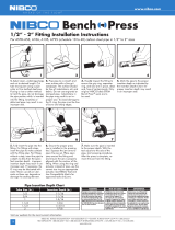
1/2” - 2” Fittings Installation Instructions
For Types K & L hard copper tubing in 1/2” to 2” sizes and annealed copper tubing in 1/2” & 3/4” sizes
NIBCO, INC NIBCO, INC NIBCO, INC
1234
5 6 7 8
1. Select clean, undamaged
copper tube and cut to desired
length. Cut tube end square
using a pipe cutter or fine-
toothed steel saw.
2. Deburr the tube inside
diameter using a rounded file or
a deburring tool.
3. Deburr the tube outside di-
ameter using a rounded file or a
deburring tool. Clean the tube end
of all dirt, oil and grease as well as
copper dust and chips from sawing.
4. Check the fitting to make sure
that the seal is in place, clean and
free of contaminants. Only original
NIBCO yellow HNBR seals are to be
used. Do not use oils or lubricants.
5. Mark the tube with the
proper insertion depth using a
permanent marker as indicated
by the Insertion Depth Chart or
NIBCO Insertion Depth Tool.
Improper insertion depth may
result in an improper seal.
6. Insert the tube into the fi tting
using a twisting motion to the
marked depth. NOTE: End of
tubing must contact stop.
7. Ensure that the proper pressing
jaws are installed in the pressing
tool and squeeze jaw arms to
open jaw set. Place open jaws
around the fi tting end and ensure
that the jaw is properly aligned
with the contour of the fi tting.
8. Make sure the tube is inserted
to the proper depth in fi tting
and with the tool at a right
angle to the tube, start pressing
procedure.
Leak Testing: Unpressed connections are located by pressurizing the system with air. When testing
with compressed air the proper maximum pressure is 15 psi. Following a successful leak test, the system
may be pressure tested up to 200 psi if required by local code requirements or project specifi cations.
Leak testing with air can be dangerous at high pressures.
Tube Insertion Depth Chart
Tube Size (In.) Insertion Depth (In.)
1/2 11/16
3/4 7/8
1 7/8
1-1/4 1
1-1/2 1-3/8
2 1-1/2
The following standards, codes and instructions should be followed when installing
NIBCO PressG fi ttings for fuel gas:
• The installation of the fuel gas system shall be in accordance with local codes, or in the absence
of local codes, in accordance with the National Fuel Gas Code NFPA 54, the LP-Gas Code NFPA
58 as applicable.
• Copper tubing shall comply with one of the following standards: Type K or L ASTM B88, ASTM
B280, or Type G ASTM B837. When annealed tube is used, rounding and sizing of the tube
ends must be performed where needed.
• Undue stress or strain on the fi ttings and the tubing is to be avoided.
• Concealed tubing and fi ttings shall be protected from puncture threats.
• If the installation requires components in addition to those supplied by the fi tting manufacturer,
those components shall be specifi ed. The instructions shall state that only the components
provided or specifi ed by the manufacturer are to be used in the installation.
• The fi tting/tubing system shall not be used as a grounding electrode for an electrical system.
• The inspection, testing and purging of the installation shall be performed using procedures specifi ed
in Part 4 of the National Fuel Gas Code NFPA 54, ANSI Z223.1, the LP-Gas Code NFPA 58
section 3.2-10 as applicable or in accordance with the requirements of the applicable local codes.
• For use with natural, propane, mixed and manufactured gasses in the vapor state, not in the liquid state.
• The fi tting/tubing system shall not be used as a means of support.
WARNING ADVERTENCIA
Read press tool operator’s
manual and fi tting manufac-
turer’s installation instructions
before using. Failure to follow
all instructions may result in
extensive property damage
and/or serious
personal injury. Call the NIBCO
Technical Service Depart-
ment at 1.888.446.4226 if you
have any
questions or need assistance.
Antes de usar, lea el Manual
del Operario de esta herra-
mienta de presión y las in-
strucciones de instalación del
acopliamiento proporcionadas
por su fabricante. Pueden
ocurrir daños materiales de
gran envergadura y lesiones
corporales de gravedad si
no se respetan todas las
instrucciones. Si tiene alguna
pregunta o desea pedir un
manual, llame al Departamento
de Servicio Técnico de NIBCO
al 1.888.446.4226.
MISE EN GARDE !
Familiarisez-vous avec le
mode d’emploi de la presse et
les instructions du fabricant
des raccords avant d’utiliser
l’appareil. Le non-respect de
leurs consignes risquerait
d’augmenter les risques de
dégâts matériels importants et/
ou de graves blessures corpo-
relles. Veuillez adresser toutes
questions éventuelles ou
demandes de mode d’emploi
à la NIBCO en composant le
1.888.446.4226.

Visit our website for the most current information.
17
NIBCO INC. WORLD HEADQUARTERS • 1516 MIDDLEBURY ST. • ELKHART, IN 46516-4740 • USA • PH: 1.800.234.0227
TECH SERVICES PH: 1.888.446.4226 • FAX: 1.888.336.4226 • INTERNATIONAL OFFICE PH: +1.574.295.3327 • FAX: +1.574.295.3455
www.nibco.com
www.nibco.com
AHEAD OF THE FLOW
®
PRESSURE TESTING:
NIBCO recommends the following leak testing procedures when installing NIBCO PressG with the leak detection feature. These test procedures allow
the installer to find un-pressed connections while the system is being tested under pressure.The uniquely designed HNBR o-ring allows fluids or gases to flow
past the seal and leak when the fitting has not yet been pressed. When the fitting has been pressed, the o-ring will create a leak-tight seal around the tube.
AIR LEAK TESTING:
1. Pressurize system up to 15 psi maximum using dry, oil free compressed air, carbon dioxide, or nitrogen.
2. Allow system pressure to stabilize for a minimum of 2 hours.
3. If system pressure has dropped, add more air to bring entire system up to 15 psi maximum. If system pressure increases above 15 psi, bleed off excess
pressure to ensure system is at a maximum pressure of 15 psi.
4. If the system pressure continues to drop, inspect all joints for un-pressed fittings. The NIBCO PressG with the leak detection feature
are designed to leak in an un-pressed condition.
5. Check all press joints for air leaks using a commercially available leak test solution or a soap and water mixture.
6. Once the system has been confirmed to be leak free, pressure can be increased to the recommended working pressure to verify system integrity.
SYSTEM INTEGRITY TESTING*:
Once a system has been confirmed to be properly installed and no press connections have been left uncrimped, the system is recommended for
testing up to the maximum non-shock working pressure of 200 psi hydrostatic.
NOTE: While NIBCO PressG products are tested to pressures as high as 600 psi, the product system rating limitation of 200 psi is in place to ensure a safety
factor of three-times proof-testing according to ASME B16.51 Copper and Copper Alloy Press-Connect Pressure Fittings.
SYSTEM INTEGRITY TESTING AT HIGHER PRESSURES*:
NIBCO PressG products can be tested at hydrostatic pressures higher than 200 CWP, not exceeding a maximum pressure of 300 psi hydrostatic for a
maximum test duration of 24 hours, when assembled and tested according to the methods prescribed above.
CAUTION: These testing parameters and protocols apply only to NIBCO products as detailed above: NIBCO accepts no responsibility or liability for any other
manufacturer’s products that may be damaged as a result of such testing.
*System integrity testing applies to leak detect and non-leak detect fittings and valves.
NIBCO® PressGTM — Crimp Integrity Testing
Instructions for Fittings
Revised 1/14/2020

Visit our website for the most current information.
18
NIBCO INC. WORLD HEADQUARTERS • 1516 MIDDLEBURY ST. • ELKHART, IN 46516-4740 • USA • PH: 1.800.234.0227
TECH SERVICES PH: 1.888.446.4226 • FAX: 1.888.336.4226 • INTERNATIONAL OFFICE PH: +1.574.295.3327 • FAX: +1.574.295.3455
www.nibco.com
www.nibco.com
AHEAD OF THE FLOW®
NIBCO® PressGTM — Frequently Asked Questions
What is the NIBCO product offering?
NIBCO PressG features a full range of copper and copper alloy fittings, commercial valves, accessories and pressing tools, jaws and
chains for use with K and L copper water tube.
What is the system temperature rating?
NIBCO PressG is rated over a temperature range of -40°F to 180°F.
What are the approved system applications?
See page 4 for a complete listing of approved applications.
How does the patented leak detection system work?
The HNBR seal has tabs that allow an uncrimped connection to leak during system testing.
What was the testing protocol for NIBCO PressG fittings and valves?
NIBCO PressG fittings and valves were subjected to a wide range of performance tests including dimensional verification, thread end
specification, hydrostatic burst strength, unrestrained pressure, static torque, bending, vacuum pressure, cyclic pressure, vibration,
thermo-cycling and dynamic torque.
Can other available pressing tools and jaws be used on the NIBCO PressG?
See page 12 for a complete listing of approved tools and jaws.
Can NIBCO PressG connection be re-crimped?
If for any reason the press cycle is interrupted, it is possible to re-crimp a NIBCO PressG connection. However, when re-crimping
the connection, the jaws must be properly aligned so that the crimp is performed in the same location as the original.
Are NIBCO PressG fittings available with solder or threaded by Press System connection?
NIBCO offers many PressG fitting combinations by soldered or threaded connection. Please note, always solder the standard wrot
connection first when possible. Prior to soldering, remove the press end HNBR o-ring, solder, allow the fitting to cool, insert the
HNBR O-ring, and then press the connection.
Can a fitting be soldered close to a PressG connection?
NIBCO recommends soldering at least 12 inches away from the Press System connection. If this length is not possible, either solder
the joint prior to connecting the press fitting or wrap the connection with a cold wet cloth.
Is NIBCO PressG approved for underground use?
In accordance with local plumbing codes, NIBCO PressG can be installed underground.
Is NIBCO PressG compatible with standard disinfectant cleaning agents?
Yes, NIBCO PressG is typically compatible. For specific cleaning agent compatibility, contact NIBCO Technical Services at the below
noted number.
Revised 1/14/2020
/


