Page is loading ...

Press Installation Instructions
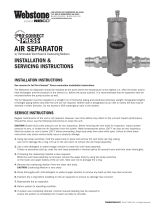
Minimum Distances Determine Insertion Depth
Installation Steps
Compatible with popular press t tools. This product is designed for use with Type K, L, and
M hard copper tubing that complies with ASTM B88 standard. See product specications for
pressure and temperature limits.
IMPORTANT: Follow all federal/national, state and local codes when installing, testing or
performing work on systems. If you have any questions or comments, please contact us.
Step 1 – Cut Tubing: Select clean, undamaged copper tube and cut to the desired length. Cut
the tube end square using a tube cutter or ne-toothed saw. Ensure that the cut is straight
and the tubing remains round. Do not press onto damaged, scratched, gouged, or otherwise
compromised tubing. Do not crimp over etched print streams on tubing. Failure to follow these
instructions may affect the performance of the joint.
Step 2 – Deburr: Using a half-round le or deburring tool, deburr the inner and outer diameters
of the tube to remove any copper shavings or lings.
Properly preparing the tubing will result in a smooth t with the press product. Failure to properly
deburr the tubing may result in damage to the product’s O-ring.
Clean the tube end of all contamination. Ensure the surface is smooth and free from scratches.
DO NOT use sandpaper or emery cloth.
Step 3 – Inspect: Check the tting to make sure that the seal is in place and is free of oil or
grease. Use only original Webstone® EPDM O-rings specied for use in Pro-Connect Press
products, contact Technical Services at the number below if a replacement O-ring is required.
Step 4 – Measure: Refer to section at top of page to determine the Press product design type
and appropriate insertion depth. Measuring from the cut, mark the approximate insertion depth
appropriate for the Press product.
Step 5 – Insert: Position the Press product on tubing and insert, ensuring it is aligned in
a straight fashion, and slowly turn until the product meets the line drawn in Step 4. If any
resistance occurs further preparation of the tubing is required. Attempting to force a fit
can dislodge or damage internal components. Water may be used as a lubricant if desired,
HOWEVER NO OTHER LUBRICANTS MAY BE USED.
Step 6 – Press Connection: Verify that the tubing is fully inserted to the mark. When installing a
ange, bolt the ange end in place before pressing the tting to the tubing.
Place the jaw of the tool at a right angle to the product and center the jaw on the ring in the
connection. Complete the connection in accordance with the tool and jaw manufacturer’s
instructions.
Leak Testing: Unpressed connections are located by pressurizing the system with air or water.
When testing with compressed air the proper maximum pressure is 15 psi. When testing with
water the successful maximum is 50 psi using potable water. Following a successful leak test,
the system may be pressure tested up to the product’s maximum pressure rating if required by
local code. Leak testing with air can be dangerous at high pressures. System testing should be
completed in accordance with requirements or codes of any federal/state/local governing body
having jurisdiction over the installation. Pressure testing should not exceed the maximum pressure
rating as noted on the product.
IMPORTANT: See table to
determine the minimum
distance between Press
connections. Failure to provide
the required distance may
distort the tubing, resulting in
an ineffective seal.
DEBURR
BEFORE
SINGLE
O-RING
DESIGN
DOUBLE
O-RING
DESIGN
AFTER
INSPECT MEASURE
A
INSERT PRESS CONNECTION
CUT TUBING
IMPORTANT: Two different tting designs
are available, see tables to determine the
correct insertion depth for a given product
before proceeding with Installation Step 4.
A
A
A
A
Single O-Ring Design
Double O-Ring Design
B
TUBING
SIZE
INSERTION DEPTH
A
MINIMUM DISTANCE
B
1/2" 3/4" 3/8"
3/4" 7/8" 3/4"
1" 7/8" 3/4"
1 1/4" 1 1/8" 1"
1 1/2" 1 3/8" 1 1/8"
2" 1 5/8" 1 3/8"
TUBING
SIZE
INSERTION DEPTH
A
MINIMUM DISTANCE
B
1/2" 1 3/8" 7/16"
3/4" 1 9/16" 13/16"
1" 1 9/16" 1"
1 1/4" 1 11/16" 1"
1 1/2" 1 7/8" 1 3/16"
2" 2 1/8" 1 3/4"
PRSI-1123
WARNING: Cancer and Reproductive
Harm - www.P65Warnings.ca.gov
(800) 225-9529 • www.webstonevalves.com ©2023 NIBCO INC., All Rights Reserved.
/