Page is loading ...

To activate 5 year limited warranty, register within 10 days of purchase at
www.thewaterwarden.com
or return completed warranty form on back page to:
Water Warden
TM
Pool Safety Products
4837 NE 12
th
Ave
Fort Lauderdale, Fl 33334

INSTALLATION INSTRUCTIONS FOR YOUR NEW
WATER WARDEN
TM
SELF-CLOSING POOL GATE
List of Components:
• 1 Water Warden
tm
Pool Gate with predrilled holes
• 2 Gate Posts, labeled “A” and “B” in illustration, with predrilled holes
• 2 Post Reinforcement Brackets with predrilled holes and black securing screw
• 2 Tru-Close hinges with screws
• 1 top-pull Magna-Latch with key lock and installation instructions
• 2 in-ground plastic feet and caps
• 1 drilling template
• 4 spring-loaded Safety Latches
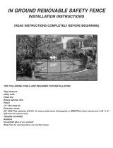
List of Tools Needed for Installation:
• Rotary hammer drill
•
5
/
8
” SDS masonry drill bit [If using a drilling guide, a
5
/
8
” x 18” masonry drill bit is needed]
• ¼” phillips head bit
• Extension cord (if necessary)
• Measuring tape
• Pencil or white chalk
• Hammer or rubber mallet
• Square and level or Water Warden
tm
Drilling Guide (available for rental from dealer where fence was
purchased)
1. Using illustration below, identify which Gate Post is “A” and which post is “B”. (use the predrilled
holes to differentiate between the two). When installing the gate posts, “A” should always be to the
right of “B”. Decide where you will install the Water Warden
tm
Pool Gate. The gate should be
installed in an easily accessible spot, on a straight side of the pool. Do not install the gate around a
curve. The gate should always be installed with the mesh material on the outside (non-pool side) of
the fence enclosure. Gate should open “out”, or towards you, when standing outside the fence.
2. Using the enclosed drilling template, mark the holes on the deck for Gate Posts “A” and “B”. These
two holes should be 32” apart, measuring from center of one in-ground pin to center of the second in-
ground pin. Facing the pool, label the left mark “B” and the right mark “A” (See illustration below).
3. The holes for Post “A” and “B” should be drilled angled 3º toward one another. For best results use
the Water Warden
tm
Drilling Guide, available for rental from the dealer where fence was purchased.
You may also use a square and level to achieve the correct angle.
4. Lay a Post Reinforcing Bracket over hole “”A”, with the square part facing upwards and the flat part
facing toward the right. The hole which is under the square part of the bracket should be aligned with
hole “A” in the deck. Using chalk or a pencil, mark through the hole on the right side of the bracket.
Remove bracket and mark this spot “C”. Drill through the spot marked “C”. This hole should be
drilled straight into the ground. Insert a plastic foot into holes “A” and “C”. Tap gently with a
hammer or rubber mallet to ensure foot is flush with the pool deck. Repeat the process for the hole
marked “B”: Lay the second Post Reinforcing Bracket over hole “”B”, with the square part facing
upwards and the flat part facing toward the left. The hole which is under the square part of the

bracket should be aligned with hole “B” in the deck. Using chalk or a pencil, mark through the hole
on the left side of the bracket. Remove bracket and mark this spot “D”. Drill through the spot
marked “D”. This hole should be drilled straight into the ground. Insert a plastic foot into holes “B”
and “D”. Tap gently with a hammer or rubber mallet to ensure foot is flush with the pool deck.
5. Insert Gate Post “A” into the appropriate Post Reinforcement Bracket, passing the steel pin on the
bottom of the post through the hole in the bottom of the square portion of the bracket. Place the post
with bracket into the hole marked “A”, ensure that the flat part of the bracket faces toward the right,
and that the hole in the flat part is aligned with hole “C” in the deck. Push down firmly to insert the
steel pin into hole “A”. Repeat with Gate Post “B”. Ensure that the flat part of the second bracket
faces toward the left and that the hole in the flat part is aligned with hole “D” in the deck. Push down
firmly to secure into the deck. Screw each Gate Post to its Reinforcement Bracket using the black
securing screw.
6. The holes marked “C” and “D” will be the first hole for the installation of the adjoining fence section
on either side of the gate.
7. Continue installing the rest of the fence system. Refer to Basic Installation Instructions included with
each fence section for details. Use the Drilling Template included with each fence section to proceed.
Attach the gate posts to the adjoining fence section poles using the pre-drilled holes and the spring-
loaded Safety Latch. Use two Safety Latches for each gate post.
8. When all fence sections are installed with correct tension, attach the gate to the gate posts. Using the
predrilled holes in post “A”, align with the predrilled holes in the gate. Lay hinge over the holes with
white label facing up, and fasten with screws. Repeat for second hinge.
9. Attach Magna-Latch to Gate/Gate Post “B”, using the pre-drilled holes in Gate Post “B” and the
installation instructions found in the Magna-Latch packet.
10. Adjust tension on hinges to ensure that gate is hanging straight.

/