Building Decks
LIFETIME LIMITED WARRANTY
Covering your use of EXTRAGREEN™ wood for as long as you own your home
or farm.
When used in an application which is consistent with the intended end use
identified on the product label or stamp and in conjunction with a residential or
agricultural structure located in the United States of America, then subject to the
conditions contained in this Warranty, your EXTRAGREEN™ wood is warranted
against such damage by termites or fungal decay as would make the lumber
structurally unfit for the applications for which it was intended.
This warranty is good from the date of purchase for as long as you
own the property on which your new EXTRAGREEN™ wood structures are built.
This warranty is applicable to the original purchaser and property owner only,
and is not transferable to any other property owner. The original consumer
purchaser will be entitled to be reimbursed for the actual, reasonable cost of new
EXTRAGREEN™ wood which is purchased to replace wood which was made
structurally unfit by damage due to termites or fungal decay. To obtain the
necessary prior approval for, and make arrangements for, this reimbursement,
the original owner must send sufficient amount of EXTRAGREEN™ wood was
originally purchased to cover the number of board feet claimed to be damaged,
to the Warrantor, at:
EXTRAGREEN™ WOOD • Warranty Claim Administrator
L.D. McFarland Company
P.O. Box 1496 • Tacoma, WA 98401-1496
When making any warranty claim you may be required to send photographs
and/or pieces of damaged wood. In addition, at the Warrantor’s request, the
Warrantor and its representatives and agents must per permitted to inspect and
test the damaged structure.
Warrantor shall not be liable hereunder for damage to EXTRAGREEN™ wood
resulting from any case other than termites or fungal decay, or for any damage
to wood which has been used in a structure outside of the U.S.; used in
foundation systems (such as the Permanent Wood Foundation, and piling, pole
or heavy timber type residential construction); used in swimming pool sidewalls;
used as fence posts, vineyard stakes or tree supports in agricultural applications;
used where immersed in salt water; used for commercial or industrial projects;
used in commonly owned property and structures such as condominiums; or
used for and application or in a way that is not consistent with the end use
identified on its original label stamp.
Warrantor shall not be liable for any installation, repair, construction, labor or
similar costs, or for any costs or damage which may be associated with the
natural characteristic of some wood to split, crack, warp, or twist. To the
maximum extent permitted by applicable law, in no event shall Warrantor be
responsible for any direct, indirect, incidental, consequential or financial damages
or expenses of any kind whatsoever, howsoever caused (whether or not due to
any deficiency or negligence in manufacturing, and whether or not relating to
loss, damage, death or injury) arising out of or relating to your purchase or use
of EXTRAGREEN™ wood.
For hem-fir, Douglas fir, and western hemlock, this warranty is null
and void unless all cut ends and bore holes were properly coated at the time of
construction with a suitable wood preservative, such as EXTRAGREEN™ End Cut
Solution, containing a minium of 1% copper. Proof of purchase of the
preservative is also required. These species are covered by this only when used
in the states of Alaska, Arizona, California, Colorado, Idaho, Montana, Nevada,
New Mexico, Oregon, Utah, Washington, Wyoming and Hawaii (except for
unincised decking which does not meet AWPA recommended standards, which
is specifically not warranted by Warrantor in Hawaii).
By purchasing EXTRAGREEN™ wood you accept this Warranty and
hereby acknowledge that this replaces all other representations, warranties,
guarantees, terms, covenants, agreements, promises, commitments, duties of
care or conditions (”Representations”), expressed or implied, statutory or
otherwise, indulging, quality or suitability, and there are no Representations
whatsoever with respect to EXTRAGREEN™ wood except the specific warranty
given hereunder. Only the Warrantor is liable under this Limited Warranty and
the directors, officers, employees and agents shall have no liability of any kind to
you or others with respect to your purchase or use of EXTRAGREEN™ wood.
SL0204
Introduction
A deck is one of the most versatile and valu-
able additions you can make to your home.
A well-made deck is great for entertaining or
for quiet family living, for showcasing a
beautiful yard or for hiding sloped or barren
land.
Building your deck yourself makes good sense.
It is a money-saving and simple project which
requires very few basic skills
and tools.
About This Book
The following
four sections in
this brochure
will guide you
in planning,
designing and building a basic deck, fencing,
and landscaping with timbers.
Great Decks: The Right Plan, The Best
Lumber
Designing the deck, choosing the type of
lumber to use and compiling a materials list
are three essential steps to building your own
deck. In this brochure, you will learn how to
plan, design, build and maintain a basic deck.
You will also learn to add railings and stairs,
as well as other advanced decking techniques.
With the proper preparation, the right tools
and wood from McFarland Cascade
®
, you’ll be
well on your way to the deck of a lifetime.
Getting Down To It
Building a deck is easy if you follow the
Six Steps to Building a Basic Deck listed
in this section.
Advanced Construction Techniques
For help in adding accessories such as
railings and stairs to your deck, or for
other advanced construction tips, turn to this
section.
Consumer Information, Tips and
Warranty
Read this section for further information
about handling treated lumber and about
general construction and maintenance.
Great Decks: The Right Plan, The Best Lumber
Careful planning is essential for your deck-
building project to be a success. There are
three steps to the planning process: Designing
the Deck, Choosing the Type of Lumber to Use
and Compiling a Materials List.
Designing the Deck
Designing your deck can be almost as much
fun as building and owning one. You can take
a stroll through your neighborhood for ideas,
read books and magazines, or just sketch out
what you have in mind. It’s fun being creative,
and there is no math involved in this stage —
just your imagination.
McFarland Cascade
®
Deck Lumber: The Obvious Choice
Choosing the right kind of lumber to use for
your deck is essential, fortunately, it is also
the easiest decision you’ll make in building
your deck.
Which Kind of Lumber Is Best For My Needs?
Whatever your requirements, McFarland
Cascade
®
has a product that will meet them,
whether your concern is for appearance,
strength or cost.
McFarland Cascade
®
offers treated framing
lumber options (the lumber used in the sup-
port and substructure of your deck) and a
variety of decking lumber (the
lumber used for the deck
surface, stairs and railings) to
suit your needs. Use the charts
on the next page to deter-
mine which framing
and decking prod-
ucts to order.
1
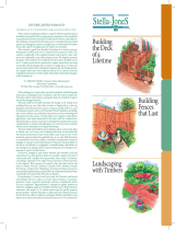
Building the
Deck of a Lifetime
Building Fences with Ease
Landscaping
with Timbers
Additional Products