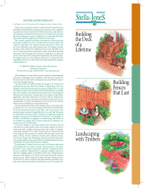
Unbranded 549000102040800 Installation guide

Type
Installation guide
Building
the Deck
of a
Lifetime
Building
Fences
with Ease
Landscaping
with Timbers
Additional
Products
CLB0209
LIFETIME LIMITED WARRANTY
Covering your use of CA treated wood for as long as you own your home
or farm.
When used in an application which is consistent with the intended end use
identified on the product label or stamp and in conjunction with a residential or
agricultural structure located in the United States of America, then subject to
the conditions contained in this Warranty, your CA treated wood is warranted
against such damage by termites or fungal decay as would make the lumber
structurally unfit for the applications for which it was intended.
This warranty is good from the date of purchase for as long as you own the
property on which your new CA treated wood structures are built. This warranty
is applicable to the original purchaser and property owner only, and is not
transferable to any other property owner. The original consumer purchaser will
be entitled to be reimbursed for the actual, reasonable cost of new CA treated
wood which is purchased to replace wood which was made structurally unfit by
damage due to termites or fungal decay. To obtain the necessary prior approval
for, and make arrangements for, this reimbursement, the original owner must
se nd su f c ient am ount of C A tre ated wood was o ri ginal ly pur chase d t o cover t he
number of board feet claimed to be damaged, to the Warrantor, at:
CA TREATED WOOD • Warranty Claim Administrator
L.D. McFarland Company
P.O. Box 1496 • Tacoma, WA 98401-1496 • www.mcfarlandcascade.com
When making any warranty claim you may be required to send photographs
and/or pieces of damaged wood. In addition, at the Warrantor’s request, the
Warrantor and its representatives and agents must per permitted to inspect and
test the damaged structure.
Warrantor shall not be liable hereunder for damage to CA treated wood
re sulti ng f ro m any c ase ot he r th an t er mite s or fung al dec ay, or fo r any d am age t o
wood which has been used in a structure outside of the U.S.; used in foundation
systems (such as the Permanent Wood Foundation, and piling, pole or heavy
timber type residential construction); used in swimming pool sidewalls; used as
fence posts, vineyard stakes or tree supports in agricultural applications; used
where immersed in salt water; used for commercial or industrial projects; used
in commonly owned property and structures such as condominiums; or used
for and application or in a way that is not consistent with the end use identified
on its original label stamp.
Warrantor shall not be liable for any installation, repair, construction, labor
or similar costs, or for any costs or damage which may be associated with
the natural characteristic of some wood to split, crack, warp, or twist. To the
maximum extent permitted by applicable law, in no event shall Warrantor be
responsible for any direct, indirect, incidental, consequential or financial damages
or expenses of any kind whatsoever, howsoever caused (whether or not due to
any deficiency or negligence in manufacturing, and whether or not relating to
loss, damage, death or injury) arising out of or relating to your purchase or use
of CA treated wood.
For hem-r, Douglas r, and western hemlock, this warranty is null and
void unless all cut ends and bore holes were properly coated at the time of
construction with a suitable wood preservative, such as End Cut Solution,
containing a minimum of 1% copper. Proof of purchase of the preservative is
also required. These species are covered by this only when used in the states
of Alaska, Arizona, California, Colorado, Idaho, Montana, Nevada, New Mexico,
Oregon, Utah, Washington, Wyoming and Hawaii (except for unincised decking
which does not meet AWPA recommended standards, which is specifically not
warranted by Warrantor in Hawaii).
By purchasing CA treated wood you accept this Warranty and hereby
acknowledge that this replaces all other representations, warranties, guarantees,
terms, covenants, agreements, promises, commitments, duties of care or
conditions (”Representations”), expressed or implied, statutory or otherwise,
ind ul gin g, q ualit y o r sui t abi lity, an d th er e ar e n o Rep re se nt at io ns w hats oe ver w it h
respect to CA treated wood except the specic warranty given hereunder. Only
the Warrantor is liable under this Limited Warranty and the directors, officers,
employees and agents shall have no liability of any kind to you or others with
respect to your purchase or use of CA treated wood.
Building Decks
Introduction
A deck is one of the most versatile and valuable
additions you can make to your home. A well-
made deck is great for entertaining or for quiet
family living, for showcasing a beautiful yard
or for hiding sloped or barren land.
Building your deck yourself makes good
sense. It is a money-saving and simple project
which requires very few basic skills and tools.
About This Book
The following four sections in
this brochure will guide
you in planning,
designing and
building a basic
deck, fencing,
and landscaping
with timbers.
Great Decks: The Right Plan,
The Best Lumber
Designing the deck, choosing the type of
lumber to use and compiling a materials list
are three essential steps to building your
own deck. In this brochure, you will learn
how to plan, design, build and maintain a
basic deck. You will also learn to add railings
and stairs, as well as other advanced decking
techniques. With the proper preparation,
the right tools and wood from McFarland
Cascade
®
, youll be well on your way to the deck
of a lifetime.
Getting Down To It
Building a deck is easy if you follow the
Six Steps to Building a Basic Deck listed in
this section.
Advanced Construction Techniques
For help in adding accessories such
as railings and stairs to your deck, or for
other advanced construction tips, turn to
this section.
Consumer Information, Tips and Warranty
Read this section for further information
about handling treated lumber and about
general construction and maintenance.
Great Decks: The Right Plan, The Best Lumber
Careful planning is essential for your deck-
building project to be a success. There are
three steps to the planning process: Designing
the Deck, Choosing the Type of Lumber to Use
and Compiling a Materials List.
Designing the Deck
Designing your deck can be almost as much
fun as building and owning one. You can take
a stroll through your neighborhood for ideas,
read books and magazines, or just sketch out
what you have in mind. It’s fun being creative,
and there is no math involved in this stage —
just your imagination.
McFarland Cascade
®
Deck Lumber:
The Obvious Choice
Choosing the right kind of lumber to use for your
deck is essential, fortunately, it is also the easiest
decision you’ll make in building your deck.
Which Kind of Lumber Is Best For My Needs?
Whatever your requirements, McFarland
Cascade
®
has a product that will meet them,
whether your concern is for appearance,
strength or cost.
McFarland Cascade
®
offers treated framing
lumber options (the lumber used in the support
and substructure of your deck) and a variety
of decking lumber (the lumber used for the
deck surface, stairs and
railings) to suit your needs.
Use the charts on the
next page to determine
which framing and
decking products
to order.
1
Building Decks
What You Need and How Many:
A Materials Worksheet
Key Measurements
First, refer to your deck design and to the
adjacent illustration. Then record your deck’s
measurements below. You will use these
measurements to compile your materials list.
Deck Length (along the house): ......... ft.
Deck width (out from the house): ...... ft.
Deck height (distance from ground
to top of decking): ................................ ft.
You may need to use the worksheet on the
right to determine the following values
Joist span (distance from house to
center of beam): ................................... ft.
Joist spacing (distance between
joist centers): ........................................ ft.
Beam span (distance between
post centers): ....................................... ft.
Now you will use these measurements to
compile your materials list.
Note: The following tables are based on a live load
of 60 pounds per square foot. If your building
code permits design with lighter loads, spans
may be longer. In this case, or if your deck will
experience heavier loads, consult an engineer or
your lumber dealer for design assistance.
In the equations below, round all fractions to
the next highest whole number.
Deck Boards
1. First, use the equation below to determine
how many lineal feet of decking lumber you
will need.
For 2x4 decking:
(deck width in inches ÷÷ 11")
X (3 x deck length) = lin. ft.
For 2x6 decking:
(deck width in inches ÷÷ 11")
X (2 x deck length) = lin. ft.
McFarland
Cascade
®
Materials for All
Outdoors
When you’ve prepared a sketch of your
new deck (refer to the illustration materials
worksheet on this page for measurements) we
will assume that the deck will be attached to
the house and that you will be using treated
hem/r lumber. This worksheet is for a deck
with no railing or stairs. See Advanced
Decking Techniques” for information about
these sometimes necessary items.
TREATED FRAMING LUMBER OPTIONS
Product Color Visual Grade Unique
Choices Characteristics
Construction Cedartone
®
Premium- Premium visual grade/
Select
extra sort 2” kiln dried prior to
treatment to attain
greatest dimensional
stability
Construction Cedartone
®
Regular sort Designed for
Pro-Framing
professional installers
(Note: All above items are treated to .21 CA for in-ground contact)
TREATED DECKING LUMBER OPTIONS
Product Color Visual Grade Unique
Choices Characteristics
Outdoor Select
®
Cedartone
®
Premium- Premium visual grade
extra sort
Douglas Fir Cedartone
®
Premium and Highest structural
Decking regular sort rating
2
Building Decks
Joist Size
2x6 2x8 2x10 2x12
Single Beam 4x6 4x8 4x10 4x12
Double Beam (2) 2x6 (2) 2x8 (2) 2x10 (2) 2x12
Cantilever 1.00’ 1.33’ 1.67’ 2.00’
Beam size: by
#of boards:
Maximum cantilever : = ft.
2. Beam length (same as deck length): = ft.
3. Now use the table below to determine your
maximum allowable beam span.
Deck Width
6’ 7’-8’ 9-10’ 11-12 13’-14’ 15’-16’ 17’-19’
6” 6.5 6
8” 8.5 7.5 7 6
10 10 9 8 7.5 6.5 6
12 11.5 10 9.5 8.5 8 7.5 7
Maximum beam span: = in.
Posts
1. First, use the equation below to determine
how many posts you will need. Note: If your
deck will have more than one beam, multiply
the total below by the number of beams.
# of posts:
[(deck length - 2 x cantilever)
÷ beam span] + 1 = posts
2. Then, use the equation below to determine
your post spacing.
JOIST
SPACING
Joists
1. Locate your decks joist span in the table
below; this will determine your joist size and
spacing.
Joist Size
2x6 2x8 2x10 2x12
12” up to 9 9-12’ 12’-16 16’-19’
16 up to 9’ 9’-12’ 12’-14’ 14’-18’
24” up to 8’ 8-10’ 10’-13’ 13’-16
Note: All 5/4decking must use 12” joist spacing.
Joist size: by
Joist spacing: in.
2. Now, use the equation below to determine
how many interior and side joists you will need.
For 16” joist spacing:
(deck length X .75) + 1 = joists
For 24” joist spacing:
(deck length X .5) + 1 = joists
3. The lengths of your joists will be as follows:
Interior joist length: deck width - 3” =
Side joist length: deck width - 1
1
/2 =
4. You will also need one ribbon joist.
Ribbon joist length
(same as deck length): =
Joist/
Beam
Depth
Joist
Spacing
Beams
1. Decide whether you will be using a single
or double beam (see Attach the Beam on page
6 for details). Then use the following table
to determine the beam size, the number of
boards per beam (in parentheses) and the
maximum allowable cantilever.
Ledger
Decking
Interior joist
Side joist
Beam
Ribbon joist
Post
BEAM SPAN
JOIST SPAN
DECK WIDTH
JOIST
CANTILEVER
DECK LENGTH
DECK HEIGHT
3
Building Decks
4. Post/beam connectors (for single beam):
# of posts = connectors
Miscellaneous
1. One quart end-cut solution.
2. One gallon water repellent for every 150 sf
of decking surface.
Also, remember to add fascia, pier blocks,
concrete/post brackets, angle brackets, concrete
and gravel as required.
Getting Down To It
Six Steps to a Basic Deck
Deck Support
1 Install the Ledger Board
2 Position Your Footings
3 Install Your Posts
Substructure
4 Attach the Beam
5 Install Your Joists
Decking
6 Lay Down Your Decking
Before beginning to build a deck, you may
need to apply for a permit check with your
local building department for this and other
code considerations.
Also see Consumer and Warranty Information
Section before beginning any construction.
Post spacing:
(deck length - 2 X cantilever) ÷÷ # of posts = ft.
3. Finally, determine the proper trimmed length of
the post.
Length of post: deck height + depth
post will be buried - 1
1
/2” = ft. in.
Note: The untrimmed post must be at least this long,
and should be longer to allow a margin for error.
Ledger Board
1. You will need one ledger board. Below, determine
its size and length.
Ledger size (same
as joist size): = by
Ledger length:
deck length - 3” = ft.
Hardware *(Galv ASTM A 153 [Fasteners]
and ASTM A 653 Class G [Connectors])
1. Joist hangers with nails:
#of interior joists =
2. Bolts (1/2” x 4” lag w/washer)*:
For ledger:
# of interior joists X 2 =
For double beam:
# of posts X 4 =
Total bolts =
3. Nails*:
For joist: # of joists X 5 =
For single beam: # of posts X 12 =
Total 16d nails =
For decking*;
with 16" joist spacing:
6(deck width in inches ÷ 11")
X[(.75 deck length in feet) + 1] =
with 24” joist spacing:
6(deck width in inches ÷ 11")
X [(.5 deck length in feet) + 1] =
Total 12d nails =
Note: We highly recommend using corrosion-
resistant deck screws. Do Not Mix the use of Hot Dipped
Galvanized and Stainless Steel. Aluminum should not be
used in direct contact with CA treated wood.
4
Building Decks
Now, lets go build a deck!
1. Install the Ledger Board
In This Step: you will prepare a at surface on your house
and will secure a ledger board to it; this will support the
interior and side joists of your deck.
Tools: framing square, tape measure, level, chalk line,
circular saw, pry bar, caulking gun, hammer, drill with
5/16bit, socket wrench.
Materials: ledger board, joist hangers with hanger nails,
caulk, flashing, framing nails. 1/2” x 4” lag bolts
Considerations: Length of ledger board = deck length minus 3”
Length of flashing = deck length
Using a framing square, mark joist hanger
positions on the ledger board.
The ledger board must be attached to a at
surface at a height 1
1
/2below the interior
oor height. Snap a level chalk line 1
1
/2below
the door threshold or, if there is no door, 1
1
/2
below the interior oor height.
(For aluminum/vinyl siding: cut
or pry away any siding below
the chalk line to expose the
rim joist of the house. Install
an L-shaped piece of metal
ashing under the siding
and over the ledger board).
Nail the ledger board temporarily in place, the
top ush with the chalk line. Since the ledger
board will be supporting much of the deck’s
weight, it is necessary to attach it securely to
the house. Drill two holes
at each midpoint between
joist hanger marks, then
permanently secure the
ledger board to the rim
joist with lag bolts. Add
ashing and caulk.
Now that the ledger board is in place,
you can install the joist hangers,
using a scrap piece of joist to
determine the proper height
of each joist hanger.
2. Position Your Footings
In This Step: you will be using string and a tape measure
to make sure that your posts and footings are correctly
positioned. This will ensure that the deck itself will be square
with the house.
Tools: tape measure, hammer, plumb bob
Materials: nails, stakes/batter boards, string
Considerations: Cantilevering setting in your footings
hides your posts from view and gives your deck a
“floatingappearance.
From your deck design, you know how far
from the house you want your posts and beam
to be. Run a string line (A) on stakes parallel
to the house at that distance. Example: for a 10’
long deck with a 2’ overhang, you would run
your line 8’ from the house.
You also know
from your
design
whether
or not
the posts
will be set
in at the
sides. Run a
string line (B)
perpendicular from
the house at that footing position. Example:
for a 10’ wide deck with 1overhang on each
side, you would start your line 4out from the
midpoint of the ledger board.
Square the positions where A & B cross by
comparing diagonal lengths. Once the dotted
lines in the diagram are the same length, your
footings will be square. Mark
your footings by dropping
a plumb bob where A
& B cross and then
pound stakes in
those spots.
Joist
spacing
3/4
Joist
spacing
1
1/2
When diagonal lengths are
equal, the footing positions
will be square.
5
Building Decks
4 Attach the Beam
In This Step: you will either lay a single beam on top of the
posts or you will attach a double beam to the sides of the posts.
Tools: pencil, framing square, tape measure, hammer,
circular saw or hand saw, drill with long 1/2” augur bit
Materials: beam board(s), framing nails, 1/2” x 4” lag
bolts for double beam or post to beam connectors with
nails for single beams
Considerations: Single or double beam?
Whether to use a single or a double beam is largely an
aesthetic decision; however, double beam boards are
generally more available, and are easier to install.
Length of beam = deck length
If the deck length exceeds the length of your beam board(s),
make sure that each splice is located at a post. Use connector
plates and bracing to keep the splice from shifting.
Transfer the joist hanger
height to the posts using
a joist and level,
or by using
string
and a line
level.
Installing a Single Beam
Since a single beam will lay
on top of
the posts, you will need
to subtract the height of
the beam from the posts.
Therefore, make a second mark on
each post below the rst mark at a
distance equal to the height of the
beam. Then cut the posts at the
second mark. Set the beam on top
of the posts and attach with connectors
and nails. Single beams are more
susceptible to swaying, so use
bracing wherever possible.
Installing
a Double Beam
A double beam
assembly uses two
boards which
3 Install Your Posts
In This Step: you will install the posts, either on pier blocks or
in the ground.
Tools: post-hole digger, shovel, wheelbarrow, level,
hammer
Materials: ready-mix concrete/pier blocks, posts, stakes/
braces, block and post connectors with nails
Considerations: Pier blocks or post-holes? Using pier
blocks is easy and effective for decks less than 3’ high;
over patios or hard, rocky soils; where ground is level; and
in colder climates.
Post-holes are sturdy, and can be used practically anywhere.
Using Pier Blocks
Set them on level, stable ground.
Then secure the posts to them
with any of several types of
connectors, making sure to
check posts for level.
Using Post-Holes
Dig holes at your footing
positions that are at least
2’ deep and are below the frost line.
For harder, rockier soils and in colder
climates, pour a bed of gravel into the
hole, place a block of treated wood on
the bed, insert the post, level
it, and ll the hole with layers
of earth and gravel, tamping
frequently and leaving a
mound at the top for drainage.
For sandy soils,
insert the post in the hole, level
the post andll hole with
concrete. Brace the post if
necessary and pour additional
concrete to form a mound for
drainage.
Note: In extreme frost heave
conditions, sonotubes may be required when
installing postsconsult your local building codes.
6
Building Decks
DOUBLE BEAM CONNECTION DETAILS
Post to 2x Beam Connection
sandwich
the posts.
Place the
top of the
beam boards
ush with
the mark
and nail
temporarily. Drill two pilot holes through
each side of post and beam boards, then
secure the entire assembly with lag bolts.
Cut the posts with a hand saw, using the beam
as a guide.
Once the beam is
installed, use a
framing square
to mark where
the interior joists
will sit on the top
of the beam.
5 Install Your Joists
In This Step: you will complete the substructure of your deck.
Side, ribbon and interior joists will provide a nailing surface
for the decking.
Tools: hammer, framing square, circular saw, tape measure
Materials: joists, framing nails
Considerations: Length of side joist
= deck width - 1
1
/2
Length of ribbon joist = deck length
Length of interior joists = deck width - 3”
Crown Side Up: each joist will have a slight bow or curve
along its vertical length the crown.Always install your
joists crown side up, so that the weight of the decking will
straighten the board rather than bow it further.
Side Joists
Nail into the edge
of the ledger
board, toenail
into the top of the
beam, then use
an angle bracket
to secure the connection
between the ledger and the joist.
Ribbon Joist
Nail into the side
joists, then use a
framing square to
mark where the
interior joists will
be attached.
Note: At this point, with the dimensions of the
deck apparent, and before you install the interior
joists, you may wish to lay black plastic or weed
fabric on the ground below the deck, to keep
undergrowth from pushing up through
the decking.
Interior Joists
To make sure that
the interior joists
are straight and
square, use the
following steps:
Galvanized
angle
bracket
(both sides)
16d
galvanized
box nails
3 x 5
galvanized
nail plate
(both sides)
Joist spacing
Joist spacing
+ 3/4
Mark both
sides
Ribbon joist
Side
joists
1
2
3
Plan View
Side View
Double Beam Spliced Connection
7
Building Decks
the distance remaining
and alter your
spacing in order to
avoid a large gap at
the end.
Secure the decking
boards at each place where they cross a joist,
using two nails or screws for 2x4s and three
nails or screws for 2x6s. When using boards
shorter than the deck length, make sure all
board ends rest on a joist, and use different
board lengths in order to stagger the splices.
When all of the decking
has been secured,
remove the bumper
board from the side
joist and snap a chalk
line across the decking on
the other side. Use this chalk
line to trim the decking boards ush
with the side joist. Use a circular saw for
this task and adjust the blade depth to cut just
the decking, not the side joist. Apply end-cut
solution to all cut ends.
If desired, you
may add a fascia
to the side and
ribbon joists for a
nished look.
Then apply a layer of quality water repellent
to all decking and exposed wood. Now your
deck is complete!
Maintenance Tips
No maintenance is needed to renew resistance to fungi
and termites. CA treated wood has a lifetime limited
warranty against these organisms.
To help protect your project against moisture damage, apply
an effective brand of water repellent as soon as your project is
finished or, for large projects, as sections are completed.
Water repellent should be re-applied every year or two.
To revitalize a dingy appearance caused by dirt, mildew
and mold, use deck brightener to clean the wood.
1. Nail into the joist
hanger.
2 Nail to the ribbon
joist, ush with
the top.
3. Align with marks on the beam and toenail
in place This will minimize bowing
Note: If the distance between the ledger and the beam
exceeds 6use blocking to keep the joists aligned.
6 And Lay Down Your Decking
In This Step: you are almost finished! Install the decking
boards, trim them and add fascia for a great, finished look.
Tools: hammer, tape measure, nail set, chalk line, circular saw
Materials: bumper board, decking boards, framing nails/
deck screws, water repellent
Considerations: Bark Side Up: lay each decking board so
that the grain pattern of the end of the board looks like a
rainbow. Why? Because if the board warps over time, it
will follow the grain, and will therefore shed water rather
than cupping to hold it.
Crown Side Out: lay each decking board so that the
crown side is out - away from the house. Why? Because
you can straighten the board by nailing each end, using a
pry bar to force the middle of the board back toward the
house until the crown is gone and then nailing it in place.
To reduce splitting of the decking while nailing, blunt the
nail points with a hammer, predrill your nail holes or use
deck screws. To avoid denting the surface of the boards,
you may wish to use a nail set.
Attach a bumper board to one of the side joists
to form a lip against which you can butt your
decking boards.
Start laying the decking from the house side,
and use nails or
shims to space the
boards slightly
for drainage (no
more than 1/16
for wet decking,
1/8for dry). As
you proceed
across your
deck, measure
Decking
Side Joist
Ribbon Joist
Fascia
8
Building Decks
Advanced Decking Techniques:
Railings, Stairs and Other
Fancy Stuff
Installing Railings
Railings enhance the beauty
and safety of your deck. They
can be simple or very elaborate
the variety of styles is almost
endless. Railings are required
for decks above a certain height; check your
local building codes for this information.
Railing Construction Tips
• Install your posts, then your top rails, side
rails and nally your rail cap.
• Use lag bolts to attach the main posts to
the deck.
• Make sure the top of the railing will be at
least 36high; some building codes require
higher railings.
• You may bevel the tops of your balusters if
they are not covered by a rail cap.
• ICBO code requires a maximum spacing of
less than 4between railing components.
Railing Styles
Rail-A-Deck
®
:
Fast, Easy
and Attractive
McFarland
Cascade
®
now
offers Rail-
A-Deck
®
,
a railing
system that
eliminates
much of the
cutting and
measuring
involved in
building a
railing.
A
B
E
D
C
Rail-A-Deck
®
Rail-A-Deck
®
All components have Lifetime limited warranty
against rot and termites.
All of the Rail-A-Deck
®
lumber has been
treated, stained and is backed by our lifetime
limited warranty against decay and termites.
Also available from McFarland Cascade
®
are
lattice panels and a variety of attractive cedar,
copper and patina post caps.
5 Main Components of Rail-A-Deck
2 x 4 Rail - Interchangeable top and bottom
rail combines the naturally inherent stability
and beauty of cedar with the termite-proof,
no-rot practicality of CA pressure treating.
31”/36/48Balusters - Finely machined, tight
grain, precision trimmed hemlock assures a
lifetime of beauty and service.
31
1
/2” x 96” x
7
/8Lattice Panel -
Inserts inside 2x4 rail top
and bottom. Double
stapled. Spacing of lath
automatically insures code compliance. May
be cut to length with radial saw as needed.
Fast and easy to install.
4 x 4 x 48
Newell Post -
9
Building Decks
Copper High Point
Post Caps Styles
Copper High Plateau
Colonial Acorn
Ball Cap High Pyramid
\Flat Cedar Cap
Suburban Pyramid
Building Stairs
Stairs link your deck to the ground; they also
connect different deck levels or span from
decks to landing. Though it may at rst seem
complicated, stair building is actually pretty
simple: determine
the rise and run,
cut your stringers
and install your
treads, either
on cleats or on
the stringers
themselves.
Use steps on cleats
when you want
an open look.
Use steps on
stringers for a
more nished
look and for
wraparound steps.
Rise and Run
The rise is the
height of each
step; the run is
its depth or tread.
The ideal rise/run
is 7/11.” Why?
Because the rise of 7” will accommodate a 2x6
face board, while 11is enough space to t
three 2x4 or two 2x6 tread boards perfectly.
As your rise decreases, your run must
increase, as follows:
Rise Run
6 15.5
5.5 16”
5 17”
4.5 18.5
4 19.5
Protect your fence and deck posts from rot
caused by collecting water while adding
the perfect nishing touch to your railing
project. Post caps are easy to install and
one size ts all. Choose from our wide
variety or proles in wood or wood/metal
combination. Each is crafted to complement
the personal aesthetics of your deck design.
McFarland Flat
10
Building Decks
Stringers: Ready-Made or Cut Your Own?
McFarland Cascade
®
offers treated Pre-Cut
Stair Stringers in 2-,3-,4- and 5-Step sizes. Of
course, all of our stringers carry a Limited
lifetime warranty against decay and termites.
Stair Building Construction Tips
1. You can hang your stringer with a
common joist hanger, if you cut a notch in
the stringer with a saw.
2. For stairs with more that 5 steps, you may
need to install posts for intermediate support.
3. If you cut your own stringers, make sure
that the bottom riser height is equal to the
rise minus the tread thickness.
4. If the steps lead to the ground, set the
stringer on a concrete or treated wood base.
5. Make sure the stringer spacing matches the
joist spacing of your deck and landings.
Stairs with Landings
Here is another case of a
project that looks more
complicated than it
really is. Think
of a landing
as a small
freestanding
deck. You
simply
run two
regular
sets of stairs
from this “deck”
to the real deck or to
the ground.
The most critical part of building stairs with
a landing is the planning. You must rst
measure where you want the stairs to begin
and end; then you can build the landing at
the proper height, and in the proper position
in relation to the deck.
Stairs with Landing Details
9 1/4”
Last riser 7” minus tread thickness (1” or 1 1/2 “)
7”
11”
13 1/16
5”
2 x 12 Stringer
1
2
4
5
3
Example of
cross bracing
Landing area
Down
Down
Stringers
Side
joist
11”
7”
Joist hanger
Stringer base toe nailed to
11” of the lower tier decking
11”
Connecting Stairs Between Tiers
Typical U Shape Landing
Layout for 7:11 Stringer
11
Building Decks
Wraparound Stairs
This kind of stair may seem complex, but its
really just two sets of regular stairs with a
connecting
area, as shown.
You will need
to build a
corner step
support using
2x8’s, and use
a bevel square
to cut your tread
boards at a 45
o
angle. Other than
that, building
wrap-around
stairs is
no more
difcult than
building
regular stairs.
Clipping Corners
Clipping the corners of your deck is an easy
way to make your deck look more interesting.
As you can see from the illustration, you will
need to make some
bevel cuts to the
beam, exterior
joists and
angled support.
You can do this
with a circular
or hand saw.
You may clip
from 2’ - 4of
the deck width
or length, as
long as in doing
so, you do not
eliminate a
post. Remember, also, that by clipping the
corner, you are removing some of the beam;
therefore, you will need to install an extra
post for support.
Cross Bracing
When building decks and landings above
a certain height, you must cross brace all
perimeter posts for added lateral stability. This
applies to decks above 6, landings above 3
and freestanding decks above 3. Check with
your local building department for other cross
bracing
requirements
in your area.
Refer to the
illustration
below when
constructing
your cross
bracing.
2 x 8
block step
support
2 x 8 joist block
7:11 pre-cut stringers
Toe nail rim joists
Beams
2’ to 4’
Rim joist
nailed to
4 x 4 post
Joist nailed to rim joist at 45
o
12
Building Fences
Great Fences: The Best Lumber:
An attractive, solid fence can be built using
a simple combination of common structural
and decorative elements
supplied by McFarland
Cascade
®
. Many of these
products are covered by
the exclusive McFarland
Cascade
®
warranty. Check
with your dealer for
details.
Common Fencing Lumber Options
Product Dimensions Length Unique
Choices Characteristics
Vertical 4” x 4posts 6-, 7- or 8-foot Used as posts to support;
Support varying grades, treated
and untreated
Horizontal 2” x 4” rails Max 8-foot See framing lumber
Support options
Appearance 1’ x 6” boards 6-foot Used as fence siding
Fencing boards; available in
square top and dog ear
50%
1/2” and 2’ x 8’ or Used as fence siding
Diagonal 1lathe 4’ x 8’ panels boards alone or in
Garden combination with
Lattice appearance fencing;
garden weave with a
larger 2-5/8” opening
70% 1/2” and 2’ x 8’ or Used as fence siding
Diagonal 1lathe 4’ x 8’ panels boards alone or in
Garden combination with
Lattice appearance fencing;
privacy weave with a
smaller 1-3/4” opening
Post Caps 4 x 4or Used to decorate and
6x 6” base protect fence posts; see
page 9 for styles
Agricultural See your McFarland
fencing Cascade
®
dealer
(Items vary in grade, treatment and warranty.)
The components of most wooden fences include
posts, rails, siding boards and post caps.
Posts
Typically 4”x4s, the posts provide vertical
structural support for the fence and are
set directly in the ground. When choosing
posts, be sure to look for McFarland Cascade
®
products with incisions on the surface of the
wood, the signature of a product that has been
treated to prevent rot from ground contact.
Rails
Horizontal structural members on a fence, the
rails, are usually 2”x4”s. Rails keep the fence
sturdy and straight and provide a nailing
surface for the siding boards. The Treated
Framing Lumber chart on page 2 outlines
your choices of color and grade.
Siding Boards
Many unique and functional fence styles are
possible with the wide range of McFarland
Cascade
®
siding boards. They range from simple
1”x 6material — straight cut or dog ear — to
more elaborate, custom cut applications. The
use of pressure treated siding board material is
highly recommended for its durability. Cedar
and redwood are other appropriate choices.
Post Cap
Post
Rail
Siding Board
13
Building Fences
Post Caps
McFarland Cascade
®
post caps will provide the
nishing touch youre looking for.
See post caps in more detail on page 10.
Getting Down To It
Building a fence is easy if you follow
these six steps. Once you get started, you’ll
nd that there are no real obstacles. Because
of the repetitive nature of fence building, your
skills will improve as your fence goes up.
1. Choosing Your Fencing Styles
and Accessories
The basic fence is formed by a series of 6’ or 8
horizontal sections that can be easily covered
in a number of attractive ways. Shown here
is one simple
fence with a basic
materials list.
Other fencing
options are also
illustrated. Most
have siding boards
that are 1” thick, such
as 1”x6s and 1”x4s.
Materials List
Solid Board
Privacy Fence
6Tall, 8’ Section
2 Posts, 4” x 4”- 8’
(One post for each next section)
2 rails, 2” x 4” - 8’
16 Siding Boards 1x 6- 6
Galvanized Fence Brackets (optional)*
Galvanized Nails*
2 Bags Ready Mix Concrete (one bag for each
next section)
*See Page 4 for recommended hardware.
2. Sketching Your Plan
Choose a fence style from the Fencing Styles
section in this brochure and then roughly sketch
out the planned location of your new fence.
Include in the drawing any property boundary
lines, structures, large plants or walkways that
may be near your fence. Make a note of the
fence height that you are considering. You may
have a 6-foot fence planned for the backyard
and a 3-foot fence in front.
Check your local zoning codes for fencing
regulations which may include height
restrictions, boundary line set-back
requirements and materials restrictions. If
your fence will be built near a property line,
check its location carefully. If you are unsure
Board on Board — Horizontal and Vertical Curved Panel Picket
Alternating Boards and Alternating Panels Diagonal Board
Horizontal Louver Lattice Top Closed Post and Board
(May also be vertical)
Ranch Rail and Post and Rail
14
Building Fences
of the location of water, gas, electrical or other
utilities that may be near your fencing project,
call your utility company for location assistance.
Measure the overall length of your planned
fence and determine how many fence sections
you will build.
A 6- or 8-foot post spacing is most economical.
Shorter sections that are needed to make the
fence come out even should be placed at the
corners or near the gates and buildings.
3. Accounting for Slope
If your fence will be built over uneven terrain
you have two choices. On ground that is
rolling and not steep, you can simply follow
its natural course. For steeper slopes, you may
wish to step the sections. Plan carefully for
the differing post and fence board lengths
that will be required for a stepped fence.
4. Digging, Setting and Aligning Posts
Placing the posts for your fence is a ve-step
process. Take care to make the posts plumb
and square. Well placed, straight posts will
greatly simplify the fence construction steps
that follow. If you are planning a gate, read
the Gate Design and Hinges Instructions on
page 17 now.
Odd Space at One End
Entire Fence Divided into Equal Intervals
Odd Space at Both Ends and Gate
8’
8’ 8’
8’ 8’
8’
8’
4’
7.6
7.6 7.6
7.6
7.6
7.6
7.6 7.6
8’
8’ 8’
8’
3.3’
8’ 8’
3.3’
5’6
4 x 4
Post
Level
Posts
Concrete
90
Brace with Boards.
Nail to Stakes
Line Levels
2 x 4 Rails
Earth or
Concrete
Siding
Boards
15
Building Fences
you set, align and brace the intermediate
posts. Intermediate post holes can be lled
with earth and gravel or, for a stronger fence
in loose or water saturated soil, use concrete.
Trim the Tops
Ensure that the tops of the fence posts are even
by trimming the tops off the posts after they
have been set - leaving room for post caps as
desired. Use end-cut solution on the cut ends.
(An alternative is to initially dig each hole to
the necessary depth to ensure even tops.)
5. Attaching Railing, Siding Boards
and Kickboards
To accommodate slight variations in post
alignment, the horizontal rails between
post should be individually measured and
cut to t. Use end-cut solution on the cut
ends. Typically, the bottom rail is installed
about six inches above the ground and the
top rail either at the top of the post or six
inches below it, if post caps are planned.
Use a line-level stretched between end posts
to ensure parallel placement, as shown in
the illustration on page 15 (Rail installation
may vary depending on the siding board
application you have chosen.)
\Dado
Heavy board fences may be made much
stronger with the use of a dado joint to
connect the rails to the posts. A chisel and
handsaw or power router can be
used to form the dado channel.
Use a straight edge guide and be
sure the work is well clamped.
The cut must be square
and smooth with
sharp edges. Be sure
to apply end-cut
solution to cut ends.
Dig the Holes
Digging the holes for your fence posts is
easily accomplished in most soils with a two-
handled clam shell digger. Rocky soil may
require the use of a digging bar to loosen the
soil. Power augers are great labor saving tools
if you have many post holes to dig.
The hole should be about 8-inches in diameter
for a 4”x4” post. The posts should be set 24 to
36 inches deep for a six-foot tall fence, deeper
for a taller fence or deep frost line (if in doubt,
consult your McFarland Cascade
®
dealer).
Place a base stone or treated wood block in the
bottom of the hole as a post foundation.
Set the Corner or End Posts
Set all of the corner or end posts rst.
Temporarily hold the posts in place by nailing
two braces from each post to stakes driven
into the ground several feet away as shown
in the illustration on page 15. Adjust the brace
as you plumb the sides of
the post with a level. To
square the posts to each
other, use a line-level
on two strings stretched
between the posts, near
the top and near ground
level, and readjust the
bracing.
Fill the Holes
Fill the corner or end post
holes with concrete. One
bag of ready-mix should
be enough for each post (more for deeper
post holes). The ll should come 1
to 2 inches above ground level and
slope away from the post
to divert water. Allow the
posts to set for two days
before proceeding.
Set the Intermediate Posts
Again, use the line-level
between the corner or
end posts as a guide as
16
Building Fences
Rails are most
easily set with
galvanized metal*
fence brackets and
nails. They may
also be butted and
toenailed, lapped,
blocked or set with
a dado. In each
case, be sure to
use galvanized*
nails. Drill pilot
holes and stagger
the nails in your
rails to avoid
splitting along
grain lines. Attach
the fence boards
according to the
style you have
selected. Using
a tight line along the bottom edge will help
ensure vertical alignment. Leave a few inches
between the bottom of the fencing boards and
the ground, or plan
for the installation of
a kickboard. A spacer
will make quick work
of evenly spacing
the boards on a
picket-style fence.
Kickboard can be added to the bottom of the
fence for added security and to keep pests out
and pets in. Use 1x 4” or 1” x 6material, as
shown, before
installing
siding boards.
6. Designing
Your Gate
Solid
construction
is the key to
a long lasting
gate. To install
a gate, the rst step
comes when you are
setting your face posts.
Posts to either side of the
gate should be absolutely
plumb and set at least
24in concrete.
The gate itself is
framed with 2”x4s and
assembled with wood
screws. Make it no
wider than 48”. Allow
1/2” clearance for the
latch and hinges.
Use a carpenter’s
square to keep
the framing true.
A diagonal brace
can be marked
and cut to t
inside the gate
frame. The top
of the brace goes
on the latch-side
corner and the
bottom on the
hinge side.
Apply gate
hardware
and
facing
boards
to the
frame
with wood
screws. When
applying the siding
boards to the
gate, begin
on the
hinge
side and
cut the
last board
ush.
Cleat
Post
Rail
Kickboard
Siding
Rail
Kickboard
*See Page 4 for recommended hardware.
17
Landscaping
TreaTed Framing Lumber OpTiOns
Product Color Visual Grade Unique
Choices Characteristics
Construction Cedartone
®
Premium- Premium visual grade/
Select
extra sort 2kiln dried prior to
treatment to attain
greatest dimensional
stability
Construction Cedartone
®
Regular sort Designed for
Pro-Framing
professional installers
Outdoor Select
®
Cedartone
®
Premium- Unincised; premium
extra sort visual grade
COmmOn LandsCape Lumber OpTiOns
Product Dimensions Length Unique
Choices Characteristics
Landscaping 4x6 8’ Used for rough
Timbers 6x6 8’ surface retaining
6x8” 8 walls and steps;
6x8” 8 CA pressure
6”x8” 8’ treated
Cherrytone Ties 3x4” 8’ CA pressure treated and
used for economical
earth retaining or fences
pressure treated and
Cherrytone Ties 3x4” 8’ Lowest cost for non-
Untreated structural, light-duty
and decorative
applications
Railroad Ties 7”x9 8’ Recycled creosote
railroad ties used for
utility landscaping and
earth retaining
Great Landscaping Projects:
The Best Lumber
Yards on sloping lots or hillsides can be made
more functional with McFarland Cascade
®
products. McFarland Cascade
®
products come
in a variety of sizes and grades to meet all of
your needs. Our 8’ treated timbers with the
“For Landscape Use Only” tagged product, are
excellent for light duty raised garden beds and
some stepped walls. For walls supporting heavy
loads or retaining signicant amounts of earth,
it is recommended that local codes be consulted
and consideration should be given to getting
professional structural guidance. Structurally
rated timbers are available through McFarland
Cascade
®
even if they might not be on the shelf
at your local retailer. Cherrytone ties make
quick work of smaller earth retaining projects.
For utility earth retention and patio paving,
recycled railroad ties may be your best choice.
McFarland Cascade
®
treated framing lumber
can also be used to construct durable benches,
planters, trellises and other garden projects.
IT’S NO CONTEST
McFarland Cascade
®
Treated Lumber
Rot Proof
Termite Proof
Added Mold Resistance
Pre-stained
Competitive Price
Uniform Appearance
Untreated Wood (Cedar, Redwood)
Potential Check/Split Resistance
Typical Lifespan: 5-7 Years in a Wet Climate
High Cost
(Items vary in grade, treatment and warranty.)
18
Landscaping
The Safety of Treated Wood
Treated wood is safe in all
applications, from raised-
bed vegetable gardens to
garden benches. Once the
CA treated is xed in the
wood cells, it is highly leach-
resistant. Pressure treated wood
is also durable and economical. Because wood
is a renewable resource, its use makes good
environmental sense.
Getting Down To It
Wooden Retaining Walls
A simple, low, wooden retaining wall on a
gentle slope with stable soil can be easily
built. Common wooden retaining walls are
constructed in two ways: timbers set into the
ground as posts to support planks, or stacked
timbers set directly on the ground.
Timber and Plank
For a timber and plank wall, digging the holes
for your posts is easily accomplished in most
soil with a two-handled clam shell digger.
Rocky soil may also require the use of a digging
bar to loosen the soil for the clam shell digger.
Power augers are great labor saving tools if you
have many post holes to dig.
Set the posts 24 to 36 inches deep for a three-
foot high wall, deeper for a deep frost line (if
in doubt, consult your McFarland Cascade
®
dealer). The hole should be about 10-inches in
diameter for a 4”x6” timber. Place a base stone
or treated wood block in the bottom of the
hole as a post foundation.
Fill the timber holes with concrete. One and
one-half bags of ready-mix should be enough
for each timber (more for deeper post holes).
The ll should come 1 to 2 inches above
ground level and slope away from the post to
divert water. Allow the timbers to set for two
days before proceeding with retaining planks
and backll (for plank material options, refer
to the McFarland Cascade
®
Treated Framing
Lumber chart on page 2. One-inch weep holes
drilled every four feet along the bottom plank
will improve drainage.
Stacked Timber
A stacked-timber retaining wall is a straight-
forward project. The bottom timber should be
set in a compacted trench below ground and
carefully leveled. Place a second timber on top
and bore a hole through both timbers with a
heavy duty drill and extension bit.
Drive a 3/4 inch pipe or rebar rod through
both timbers and well into the ground. Stagger
the joints as you add timbers and spike them
together on each side of every joint.
For drainage,
occasionally leave
a 1/4to 1/2” space
at the joint between
timbers.
Retaining walls built
on very unstable
soil may require the
Wall
Timbers
Rebar
Fill
Original
Slope
Excavation
Line
19
  • Page 1 1
  • Page 2 2
  • Page 3 3
  • Page 4 4
  • Page 5 5
  • Page 6 6
  • Page 7 7
  • Page 8 8
  • Page 9 9
  • Page 10 10
  • Page 11 11
  • Page 12 12
  • Page 13 13
  • Page 14 14
  • Page 15 15
  • Page 16 16
  • Page 17 17
  • Page 18 18
  • Page 19 19
  • Page 20 20
  • Page 21 21
  • Page 22 22
  • Page 23 23
  • Page 24 24

Unbranded 549000102040800 Installation guide

Type
Installation guide

Ask a question and I''ll find the answer in the document

Finding information in a document is now easier with AI