Page is loading ...

NX™ SWITCHES
INSTALLATION INSTRUCTIONS
9601 Dessau Road, Building One | Austin, TX 78754 Toll Free: 888-698-3242 | Fax: 512-450-1215 | www.hubbell-automation.com 3457B 3.16.2016
PRECAUTIONS
• Read and understand all instructions before beginning installation.
• CAUTION: FOR USE WITH CLASS 2, LOW VOLTAGE SYSTEMS ONLY. DO NOT USE IN HIGH VOLTAGE
APPLICATIONS.
• NOTICE: For installation by a licensed electrician in accordance with National and/or local Electrical Codes and the
following instructions.
• Conrm device ratings are suitable for application prior to installation. Use of device in applications beyond
its specied ratings or in applications other than its intended use may cause an unsafe condition and will void
manufacturer’s warranty.
• Use only approved materials and components (i.e. wire nuts, electrical box, etc.) as appropriate for installation.
• ALL EXCESS CABLE MUST BE REMOVED FROM WALL BOX PRIOR TO INSTALLATION. Connection between CAT5
cable and switch connection port must remain straight and true without interference or pressure from excess or
misaligned cable.
• NOTICE: Do not install if product appears to be damaged.
SAVE THESE INSTRUCTIONS!
DESCRIPTION
Hubbell Control Solutions NX Switches provide manual control of the NX System. All NX Switches provide plug and play
integration with the NX Room Controller.
SPECIFICATIONS
Power Requirements Powered by NX Room Controller using wiring adapter and plenum rated CAT5 plug and
play cables (sold separately)
Environment Indoor use only
Mounting Fits standard decorator style wall plates (sold separately)
Warranty Five-year limited warranty

INSTALLATION
1. Prepare the installation site as necessary, to install the switch.
2. Plug the CAT5 cable into any available SmartPORT™ on the NX™ Room Controller (See Figure 3). Verify solid snap-in connection.
3. Route the CAT5 cable from the Room Controller to enter the RJ45 port on the switch (See Figure 1).
NOTE: Low voltage wiring must be isolated from line voltage wiring. Consult National and Local Electrical Codes for conduit
requirements.
4. Set the switch address to number 1 on the rotary address switch. Additional switches to be daisy chained on the same SmartPORT
must be set to unique addresses i.e. 2, 3, 4, etc. A maximum of 8 switches can be connected to one SmartPORT. (See Figure 2)
5. Plug the CAT5cable into the switch. Verify solid snap-in connection.
6. If multiple switches are ganged together in the same wall box, daisy chain them together using the 3”jumper cable. Switches located
in dierent areas may also be daisy chained using longer CAT5 cables. Verify solid snap-in connection(s).
7. REMOVE ALL EXCESS CABLE FROM WALL BOX PRIOR TO INSERTION OF SWITCH(ES). Connection between cable and switch
connection ports must remain straight and true without interference or pressure from excess or misaligned cable. It is recommended
to test the functionality of the switch(es) prior to insertion in the wall box.
Page 2
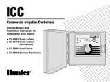
Figure 1: Back View of Switches
Figure 3: NX Switches connected to Room Controller SmartPORT
72-00547
Switches utilize a rotary dial located behind
the switch face for manual addressing of each
switch. See #4 above.
Figure 2: View Behind Switch Face
Conguration Push Button
Rotary Address Switch
LED Conguration Indicator
/