Page is loading ...


00

Lighthouse Worldwide Solutions
ApexRemote Airborne Particle Counter
Operating Manual

Copyright © 2014-2016 by Lighthouse Worldwide Solutions. All rights reserved. No part of this
document may be reproduced by any means except as permitted in writing by Lighthouse
Worldwide Solutions.
The information contained herein constitutes valuable trade secrets of Lighthouse Worldwide
Solutions. You are not permitted to disclose or allow to be disclosed such information except as
permitted in writing by Lighthouse Worldwide Solutions.
The information contained herein is subject to change without notice. Lighthouse Worldwide
Solutions is not responsible for any damages arising out of your use of the LMS program.
LMS™, LMS Express™, SIU™ and ApexRemote™ are trademarks of Lighthouse Worldwide
Solutions.
Microsoft®, Microsoft Windows™, and Excel™ are trademarks of Microsoft Corporation.
Manufactured by:
Lighthouse Worldwide Solutions
1221 Disk Drive
Medford, Oregon 97501
LWS Part Number 248083447-1 Rev1

EU DECLARATION OF CONFORMITY
Manufacturer’s Name: Lighthouse Worldwide Solutions, Inc.
Manufacturer’s Address: Lighthouse Worldwide Solutions, Inc.
1221 Disk Drive
Medford, OR 97501 USA
Declares that the product:
Product Name: REMOTE Airborne Particle Counter
Model Number(s): ApexRemote Series
Conforms to the following Product Specifications:
SAFETY EN61010-1:2010 Safety Requirements for Electrical Equipment for
Measurement, Control, and Laboratory Use Part 1:
General Requirements IEC 61010-1:2010
Safety Requirements for Electrical Equipment for
Measurement, Control and Laboratory Use, Part 1:
General Requirements
LASER SAFETY Guidance on Laser Products: Conforms to FDA 21 CFR
Chapter 1 Subchapter 1
EMC EN61326-1:2006 Electrical Equipment for Measurement, Control and
Laboratory Use EN 61326-1:2006
UL 61010A-1 - UL Standard for Safety Electrical Equipment for Laboratory Use; Part 1: General Requirements
Replaces UL 3101-1
Supplementary information
The product herewith complies with the requirements of the Low Voltage Directive 73/23/EEC amended by
Directive 93/68/EEC and the EMC Directive 89/336/EEC amended by Directive 93/68/EEC and carries the
CE marking accordingly.
Hanford Choy - Director Engineering
Fremont, CA. Feb 19, 2015
CAN/CSA C22.2
No. 1010.1-1992
IEC 60825-1 Am. 2
IEC 60601-2-22
(Laser Notice 50)


00
248083447-1 Rev 1 t-i
Table of Contents
About this Manual
Text Conventions ................................................................................................................ i
Additional Help ................................................................................................................... i
Chapter 1 General Safety
Safety Considerations .................................................................................................... 1-1
LASER Safety Information ........................................................................................... 1-1
Electrostatic Safety Information .................................................................................... 1-2
Chapter 2 Introduction
Overview ........................................................................................................................ 2-1
Description ..................................................................................................................... 2-1
Accessories .................................................................................................................... 2-2
ApexRemote Specifications ........................................................................................... 2-3
Chapter 3 Get Started
Unpacking and Initial Inspection ................................................................................... 3-1
Identify the ApexRemote Model ................................................................................... 3-1
Compare Contents .......................................................................................................... 3-1
Configuration Kit ........................................................................................................... 3-1
Software and SmartPort cable Setup ................................................................. 3-2
Date Settings: ..................................................................................................... 3-6
Factory Standard Settings .............................................................................................. 3-6
ApexRemote PoE Model: .................................................................................. 3-6
ApexRemote Serial: ........................................................................................... 3-7
Operation ....................................................................................................................... 3-9
Understanding the LEDs .................................................................................... 3-9
Chapter 4 Communications
ApexRemote Serial DIP Switches ................................................................................. 4-1
DIP Switch Definitions ...................................................................................... 4-2
Communication Modes .......................................................................... 4-2
DIP Switch Addressing .......................................................................... 4-3

Lighthouse ApexRemote Operating Manual
t-ii 248083447-1 Rev 1
Communicating with ApexRemote Serial Instrument ................................................... 4-3
Serial Data / Power Port ..................................................................................... 4-3
RS-485 Communications ....................................................................... 4-5
Communicating with ApexRemote PoE Instrument ..................................................... 4-6
ApexRemote PoE Communications .................................................................. 4-6
Ethernet Settings: ................................................................................... 4-7
ApexRemote Web Page Interface .................................................................................. 4-8
Chapter 5 Maintenance Procedures
Introduction .................................................................................................................... 5-1
Safety ............................................................................................................................. 5-1
Maintenance ................................................................................................................... 5-1
Calibration ......................................................................................................... 5-1
Zero Count Test ............................................................................................................. 5-1
Fault Isolation ................................................................................................................ 5-2
Instrument Service Report ............................................................................................. 5-2
Chapter 6 Program with the MODBUS Protocol
DIP Switches .................................................................................................................. 6-1
Protocol Settings ............................................................................................................ 6-1
Power On/Auto Start ...................................................................................................... 6-1
Running the Instrument Using MODBUS ..................................................................... 6-2
AUTOMATIC Counting Mode ......................................................................... 6-2
Configuring with the MODBUS Protocol ..................................................................... 6-3
Setting the Real Time Clock .............................................................................. 6-3
Changing the Default Instrument Parameters .................................................... 6-4
Using Sensor Setting Registers .............................................................. 6-4
Location (Register 40026) ..................................................................... 6-5
Hold Time (Registers 40031, 40032) .................................................... 6-5
Sample Time (Registers 40033, 40034) ................................................ 6-5
Alarm Enable Registers ..................................................................................... 6-6
Enable Alarming for a Channel ............................................................. 6-7
Threshold Setup Registers ................................................................................. 6-7
Setting the Alarm Threshold Value ....................................................... 6-8
Chapter 7 Install
Install the ApexRemote ................................................................................................. 7-1
Installation Basics: ............................................................................................. 7-1
Installing the SmartBracket/ApexRemote ......................................................... 7-1
Tools/Hardware Required: ..................................................................... 7-1
Installing ApexRemote without SmartBracket .................................................. 7-4
Communication Ports .................................................................................................... 7-6

Table of Contents
248083447-1 Rev 1 t-iii
ApexRemote Serial: ........................................................................................... 7-6
ApexRemote PoE: .............................................................................................. 7-6
Power Consumption: .......................................................................................... 7-6
Outlet Port (Vacuum Input) ............................................................................... 7-6
SmartBracket Settings ........................................................................................ 7-7
Realtime LMS Pro/Pharma Data Download .................................................................. 7-8
Shipping Instructions ..................................................................................................... 7-8
Appendix A ApexRemote MODBUS Register Map v1.50
COMM Settings ............................................................................................................ A-1
Supported MODBUS Commands ................................................................................. A-1
Sensor Settings Registers .................................................................................. A-2
Device Options ..................................................................................... A-6
Device Status ........................................................................................ A-6
Alarm Enable Registers .................................................................................. A-10
Enable Alarming for a Channel .......................................................... A-11
Threshold Setup Registers .............................................................................. A-11
Setting the Alarm Threshold Value .................................................... A-12
Data Registers ............................................................................................................. A-12
Device Status Word ........................................................................................ A-16
Data Enable Registers ..................................................................................... A-17
Appendix B Limited Warranty
Limitation Of Warranties: .............................................................................................. B-1
Warranty Of Repairs After Initial Two (2) Year Warranty: .......................................... B-1
Index

Lighthouse ApexRemote Operating Manual
t-iv 248083447-1 Rev 1

00
248083447-1 Rev 1 i
About this Manual
This manual describes the detailed operation and use of the Lighthouse
ApexRemote Airborne Particle Counters.
Text
Conventions
The following typefaces have the following meanings:
Note:
A note appears in
the sidebar to give extra
information regarding a
feature or suggestion.
italics Represents information not to be typed
or interpreted literally. For example, file
represents a file name. Manual titles are
also displayed in italics.
WARNING:
A warning
appears in a paragraph
like this and indicates a
condition, which if not
met, could cause serious
personal injury or death,
and damage to the
instrument.
boldface Introduces or emphasizes a term.
Courier font Indicates command syntax or text
displayed by the diagnostic terminal.
Bold Courier Indicates commands and information that
the user type.
Helvetica Italics Indicates a comment on a command or
text output.
Additional
Help
For more information about Lighthouse ApexRemote Airborne Particle
Counters, contact Lighthouse Worldwide Solutions.
Service and Support
Tel: 1-800-945-5905 (USA Toll Free)
Tel: 1-541-770-5905 (Outside of USA)

Lighthouse ApexRemote Operating Manual
ii 248083447-1 Rev 1

00
248083447-1 Rev 1 1-1
1General Safety
Safety
Considerations
Warnings and cautions are used throughout this manual and the reader
should become familiar with the meaning of a warning before
operating the particle counter. Most warnings will appear in the left
margin of the page next to the subject or step to which it applies. Take
care when performing any procedures preceded by or containing a
warning. The classifications of warnings are defined as follows:
WARNING: There are
no user-serviceable
components inside the
particle counter
• LASER - pertaining to exposure to visible or invisible LASER
radiation
• Electrostatic - pertaining to electrostatic discharge
• Network Connect - pertaining to communication ports and
instrument damage
LASER Safety
Information
This product is considered to be a Class 1 LASER product (as defined
by FDA 21 CFR, §1040.10) when used under normal operation and
maintenance. Performing service on the internal sensor can, however,
result in exposure to invisible radiation.
WARNING: The use
of controls, adjustments
or procedures other than
those specified within
this manual may result in
personal injury and/or
damage to this
instrument.
The particle counter has been evaluated and tested in accordance with
EN 61010-1:2012, “Safety Requirements For Electrical Equipment for
Measurement, Control and Laboratory Use” and IEC 60825-1:2007,
“Safety of LASER Products”.
For further technical assistance, contact our Technical Support Team at
800-945-5905 (USA Toll Free), 541-770-5905 (Outside of USA).

Lighthouse ApexRemote Operating Manual
1-2 248083447-1 Rev 1
WARNING: The use of controls, adjustments or procedures
other than those specified within this manual may result in
personal injury and/or damage to this instrument. Attempts
by untrained personnel to disassemble, alter, modify or
adjust the electronics or optics may result in personal injury
and damage to the instrument and will void its warranty.
There are no user-serviceable components inside the
particle counter. Only factory authorized service personnel
should repair or service this instrument and its optical
system.
Review Lighthouse specifications before installing a DC
power supply, gateway or PoE switch that will be
designated as a power source for the ApexRemote.
Attempting to use under-rated power source equipment can
expose the instrument, adjacent equipment and the user to
dangerous shock and fire hazards. Failure to meet the
specifications as provided by Lighthouse Worldwide
Solutions will void the instrument Warranty and CE
certification and may cause serious personal injury.
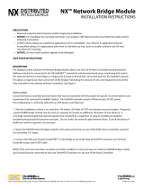
WARNING: The
ApexRemote PoE can
use a standard Ethernet
Cat6 cable and separate
24V AC-DC power
supply. It connects to the
round connector shown
on the right in Figure 1-1.
The symbol shows the
voltage and polarity of
supplied power. Handle
with care and keep away
from water or conductive
liquids.
Figure 1-1 SmartPort, Ethernet and 24VDC Power Connectors
Electrostatic
Safety
Information
Electrostatic discharge (ESD) can damage or destroy electronic
components. Therefore, any service or maintenance work should be
done at a static-safe work station. A static-safe work station requires an
ESD consultant to evaluate the work environment and propose the
equipment and apparel needed for just such a work station to be
successful.

00
248083447-1 Rev 1 2-1
2Introduction
Overview This operating manual introduces the Lighthouse ApexRemote
family of PoE and Serial models of Airborne Particle Counters and
includes instructions for inspecting, installing, using and maintaining
the instrument.
Description The ApexRemote instrument comes standard with two particle-size
channels based on channel sizes ordered and one of two flow rates of
0.1 or 1.0 CFM. Optionally, the ApexRemote can be shipped with up
to four particle-size channels. Figure 2-1 shows the standard
configuration as well as the optional display configuration. Table 2-1
lists features and specifics about the ApexRemote.
Figure 2-1 ApexRemote Airborne Particle Counter
The instrument uses a LASER diode light source and LASER beam
shaping optics to illuminate a cross section of the air flow path. As
particles move along this path, they cross the LASER beam and scatter
light. The light scattered is collected by an optical imaging system onto
a photodiode. The photodiode converts the image into a current which
is converted to a voltage and amplified by an electronic circuit.
The result is the electronic circuit outputs a voltage pulse each time a
particle crosses the LASER beam. The amplitude of the voltage pulse
is proportional to the light scattered which in turn is proportional to the

Lighthouse ApexRemote Operating Manual
2-2 248083447-1 Rev 1
size of the particle.
The voltage pulses created by the particles are then processed by
additional electronics that analyze the height of each pulse and
therefore the size of each corresponding particle. The result is that the
number of particles of various sizes is determined.
These instruments are effective in both ultra-clean areas (such as ISO
Class 1 or Grade A) and also in more traditional cleanzones rated as
ISO Class 3 or higher. Refer to Specifications tables in this manual for
additional instrument information.The ApexRemote line of Airborne
Particle counters was created for continuous operation 24 hours per
day, 7 days per week.
Note: Use of the terms
ApexRemote and
instrument are
interchangeable.
Using an external vacuum source, the instrument provides versatile
mounting options and can be installed where space is at a premium.
The ApexRemote integrates seamlessly with large facility
monitoring/management systems and transfers particle count data
using RS-485 (using MODBUS RTU or ASCII protocols) or PoE
(Power over Ethernet) via MODBUS/TCP.
Accessories Several optional accessories can be ordered to tailor the instrument to
specific needs. These accessories are listed here:
• (Specify Flow Rate) Isokinetic Sampling Probe
• Sample Tubing, per foot
• Cable, per foot
•SmartBracket
• 0.1μm Purge Filter Assembly (Specify Flow Rate) with Tubing
• Configuration Kit (one included per order):
•SmartPort cable
• 24VDC Power Supply for the SmartPort cable
• Software and Operating Manual on CD
• Read Me First
•Parts List

Introduction
248083447-1 Rev 1 2-3
ApexRemote
Specifications
Size Range 0.2 - 2.0 μm
Channel Thresholds Standard 2-channel: 0.2μ, 0.3μm
Standard 4-channel: 0.2μ, 0.3μ, 0.5μ, 1.0ȝm
Optional 6-channel: 0.2μ, 0.3μ, 0.5μ, 0.7μ, 1.0μ,
2.0ȝm
Flow Rate 0.1 CFM (2.83 LPM)
Counting Efficiency 50% (per ISO 21501-4)
Data Storage Rotating Buffer, 3000 records
Light Source LASER diode
Zero Count Level <1 count/5 minutes (per ISO 21501-4)
Calibration NIST Traceable
Communication Modes MODBUS ASCII; MODBUS RTU; MODBUS
TCP
ISO Probe Maximum
Tubing Length
From ApexRemote Inlet to ISO Kinetic Probe =
10 ft (3.0 M)
Supporting Software LMS Pharma/Pro v7.3.1 or higher, LMS Express
7.5 or higher; LWS Instrument Setup Tool 1.3.5 or
higher
Power Input Requirements 24VDC ±5% @ 250mA via LMS 485 Gateway
for ApexRemote Serial, PoEswitch for
ApexRemote PoE (IEEE 802.3af compliant) or
AC/DC supply for ApexRemote PoE
Power Supply
Specifications
Optional Listed LPS Power Supply, Output 20-
26VDC 400mA (10W) min, ApexRemote PoE
Enclosure Stainless Steel, VHP compatible
Dimensions 6.38” (w) x 4.59” (h) x 2.94” (d) [16.21 x 11.66 x
7.5 cm]
Weight 1.4 lbs (0.63 kg)
Operating Temp/RH 50° F to 104° F (10° C to 40° C) / 20% to 95%
non-condensing
Storage Temp/RH 14° F to 122° F (-10° C to 50° C) / Up to 98% non-
condensing
Table 2-1 ApexR02 Specifications

Lighthouse ApexRemote Operating Manual
2-4 248083447-1 Rev 1
Size Range 0.3 - 5.0 μm
Channel Thresholds Standard 2-channel: 0.3μ, 0.5μm
Standard 4-channel: 0.3μ, 0.5μ, 1.0μ, 5.0ȝm
Optional 6-channel: 0.3μ, 0.5μ, 0.7μ, 1.0μ, 3.0μ,
5.0ȝm
Flow Rate 0.1 CFM (2.83 LPM)
Counting Efficiency 50% (per ISO 21501-4)
Data Storage Rotating Buffer, 3000 records
Light Source LASER diode
Zero Count Level <1 count/5 minutes (per ISO 21501-4)
Calibration NIST Traceable
Communication Modes MODBUS ASCII; MODBUS RTU; MODBUS
TCP
ISO Probe Maximum
Tubing Length
From ApexRemote Inlet to ISO Kinetic Probe =
10 ft (3.0 M)
Supporting Software LMS Pharma/Pro v7.3.1 or higher, LMS Express
7.5 or higher; LWS Instrument Setup Tool 1.3.5 or
higher
Power Input Requirements 24VDC ±5% @ 250mA via LMS 485 Gateway
for ApexRemote Serial, PoEswitch for
ApexRemote PoE (IEEE 802.3af compliant) or
optional AC/DC supply for ApexRemote PoE
Power Supply
Specifications
Optional Listed LPS Power Supply, Output 20-
26VDC 400mA (10W) min, ApexRemote PoE,
only
Enclosure Stainless Steel, VHP compatible
Dimensions 6.38” (w) x 4.59” (h) x 2.94” (d) [16.21 x 11.66 x
7.5 cm]
Weight 1.4 lbs (0.63 kg)
Operating Temp/RH 50° F to 104° F (10° C to 40° C) / 20% to 95%
non-condensing
Storage Temp/RH 14° F to 122° F (-10° C to 50° C) / Up to 98% non-
condensing
Table 2-2 ApexR03 Specifications

Introduction
248083447-1 Rev 1 2-5
Size Range 0.5 - 5.0 μm
Channel Thresholds Standard 2-channel: 0.5μ, 5.0μm
Standard 4-channel: 0.5μ, 1.0μ, 5.0μ, 10.0ȝm
Optional 6-channel: 0.5μ, 0.7μ, 1.0μ, 3.0μ, 5.0μ,
7.0μ, 10.0ȝm
Flow Rate 0.1 CFM (2.83 LPM)
Counting Efficiency 50% (per ISO 21501-4)
Data Storage Rotating Buffer, 3000 records
Light Source LASER diode
Zero Count Level <1 count/5 minutes (per ISO 21501-4)
Calibration NIST Traceable
Communication Modes MODBUS ASCII; MODBUS RTU; MODBUS
TCP
ISO Probe Maximum
Tubing Length
From ApexRemote Inlet to ISO Kinetic Probe =
10 ft (3.0 M)
Supporting Software LMS Pharma/Pro v7.3.1 or higher, LMS Express
7.5 or higher; LWS Instrument Setup Tool 1.3.5 or
higher
Power Input Requirements 24VDC ±5% @ 250mA via LMS 485 Gateway
for ApexRemote Serial, PoEswitch for
ApexRemote PoE (IEEE 802.3af compliant) or
optional AC/DC supply for ApexRemote PoE
Power Supply
Specifications
Optional Listed LPS Power Supply, Output 20-
26VDC 400mA (10W) min, ApexRemote PoE,
only
Enclosure Stainless Steel, VHP compatible
Dimensions 6.38” (w) x 4.59” (h) x 2.94” (d) [16.21 x 11.66 x
7.5 cm]
Weight 1.4 lbs (0.63 kg)
Operating Temp/RH 50° F to 104° F (10° C to 40° C) / 20% to 95%
non-condensing
Storage Temp/RH 14° F to 122° F (-10° C to 50° C) / Up to 98% non-
condensing
Table 2-3 ApexR05 Specifications

Lighthouse ApexRemote Operating Manual
2-6 248083447-1 Rev 1
Size Range 0.3 - 5.0 μm
Channel Thresholds Standard 2-channel: 0.3μ, 0.5μm
Standard 4-channel: 0.3μ, 0.5μ, 1.0μ, 5.0μm
Optional 6-channel: 0.3μ, 0.5μ, 0.7μ, 1.0μ, 3.0μ,
5.0μm
Flow Rate 1.0 CFM (28.3 LPM)
Counting Efficiency 50% (per ISO 21501-4)
Data Storage Rotating Buffer, 3000 records
Light Source LASER diode
Zero Count Level <1 count/5 minutes (per ISO 21501-4)
Calibration NIST Traceable
Communication Modes MODBUS ASCII; MODBUS RTU; MODBUS
TCP
ISO Probe Maximum
Tubing Length
From ApexRemote Inlet to ISO Kinetic Probe =
10 ft (3.0 M)
Supporting Software LMS Pharma/Pro v7.3.1 or higher, LMS Express
7.5 or higher; LWS Instrument Setup Tool 1.3.5 or
higher
Power Input Requirements 24VDC ±5% @ 250mA via LMS 485 Gateway
for ApexRemote Serial, PoEswitch for
ApexRemote PoE (IEEE 802.3af compliant) or
optional AC/DC supply for ApexRemote PoE
Power Supply
Specifications
Optional Listed LPS Power Supply, Output 20-
26VDC 400mA (10W) min, ApexRemote PoE,
only
Enclosure Stainless Steel, VHP compatible
Dimensions 6.38” (w) x 4.59” (h) x 2.94” (d) [16.21 x 11.66 x
7.5 cm]
Weight 1.6 lbs (0.73 kg)
Operating Temp/RH 50° F to 104° F (10° C to 40° C) / 20% to 95%
non-condensing
Storage Temp/RH 14° F to 122° F (-10° C to 50° C) / Up to 98% non-
condensing
Table 2-4 ApexR3 Specifications
/