Page is loading ...

763 WI-FI MODULE
Installation Guide
DESCRIPTION
1. Remove power from the panel.
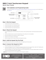
2. Remove the 763 cover by pressing the triangle-shaped
button at the end of the 763. See Figure 1.
3. Connect the included 3’ cable to the 6-pin header on the
763.
4. Route the other end of the cable through the 763 cut-out
then through the panel enclosure box, and connect it to
the EXP header on the panel. See Figures 2 and 3.
1
The 763 Wi-Fi Module allows
you to add Wi-Fi alarm signal
communication to XT30/XT50
Series and XR150/XR550 Series
panels.
The 763 connects to compatible
panels using the included cable and
operates at 12VDC from the panel
power supply.
The 763 also provides a green LED
that displays to indicate successful
network connection.
Compatibility
• All DMP XT30/XT50 Series
control panels with Version 124
firmware or higher and Level L
hardware or newer.
• All DMP XR150 Series control
panels with Version 112 firmware
or higher and Level F hardware or
newer.
• All DMP XR550 Series control
panels with Version 112 firmware
or higher.
• 2.4 GHz b/g/n
What is Included?
• One 763 Wi-Fi Module PCB in a
Two-Part Housing
• One 3’ Cable
Figure 1: 763 Wi-Fi Module
MOUNT THE 763
Avoid mounting the 763 near metal objects or inside a metal
enclosure. Select a dry place to protect the 763 from environmental
elements.
1. With the 763 open and connected to the panel, hold the
transmitter base containing the 763 PCB in the desired
location.
2. Use the supplied screw to secure the base to a surface. See
Figure 4.
3. Snap the 763 cover back onto the base.
CONNECT THE 763
2
EXP
LOAD
RESET
ETHERNET
CELL MODULE
OUTPUTS
1
2
3
4
RESET
LOAD
EXP
Figure 3: 763 to XR150/XR550
Series Panel
Figure 2: 763 to an XT30/XT50
Series Panel
Figure 4: Mount the 763
Mounting
Hole

2 763 INSTALLATION GUIDE | DIGITAL MONITORING PRODUCTS
PROGRAM THE 763 IN NETWORK OPTIONS
Network Options are provided to define network communication for the panel. Keep in mind, WIFI must
be selected as the COMM TYPE in the COMMUNICATION menu in order for WIFI SETUP to display. Also,
IP addresses and port numbers may need to be assigned by the network administrator. Refer to the panel
programming guide when needed.
1. Connect a keypad to the PROG header on the panel. If you are using a DMP wireless panel, ensure
panel communication has been established and the User Menu displays on an associated keypad before
continuing.
2. Reset the panel by fully placing the reset jumper on the RESET header for two seconds, then remove the
reset jumper and place it on just one pin.
3. Enter 6653 (PROG) at the keypad to access the PROGRAMMER menu.
4. Press CMD until NETWORK OPTIONS displays and press any select key or area.
3
WPS
1. Select WPS to automatically connect to a WPS-enabled router.
2. When SEARCHING displays on the keypad, press the WPS button on the router. Searching
may take up to two minutes, or until a connection has been made. If a connection cannot be
established, WPS FAILED RETRY? NO YES displays. Press the fourth select key or area to RETRY
or press the third select key or area to return to WPS LIST MANUAL.
LIST
1. Select LIST to display a list of networks on the keypad. The keypad searches and displays a list of
available networks.
2. Press CMD to scroll through the list of available networks. Press any select key or area to select a
network.
3. Enter the W/L KEY: ************* and CONNECTING displays. CONNECTED displays on the key-
pad when the connection is successful. NOT CONNECTED displays when the connection is not
successful. Press CMD to return to WPS LIST MANUAL.
MANUAL
1. Select MANUAL to enter the name of the desired network.
2. Enter the SSID (network name) and press CMD. See Aditional Information .
3. If the network was found, SSID FOUND displays. If the network was not found, SSID NOT FOUND
displays. Press CMD to return to WPS LIST MANUAL.
TEST
Select TEST to test the selected network connection.
5. At WIFI SETUP, press any select key or area and WPS LIST MANUAL displays. (Press CMD to display
TEST.)
6. When the panel is successfully connected to a network, W/L SECURITY displays. The default wireless
security type is WPA-PSK. Press a select key or area to display the additional options (WEP WPA NONE).
7. If WIFI was selected as the COMM TYPE and NONE was selected as the W/L SECURITY type, W/L
KEY will display. Enter the key provided by the network router’s programming. WEP requires a network
password of 10 characters (WEP64) or 26 characters (WEP128), using a combination of numbers,
uppercase letters, and lowercase letters. See Additional Information.
8. At DHCP, select YES if the panel uses a dynamic IP address. The addresses will populate automatically as
you CMD through the menu items. Select NO if you need to enter specific address.
9. Press CMD until STOP displays. Press any select key or area to save all programming.
TEST THE 763 SIGNAL STRENGTH
4
1. Access the diagnostics menu by entering 2313 (DIAG) in the keypad.
2. Press CMD until WIFI SIGNAL displays and press any select key or area.
SIGNAL, the network name, and 0-7 bars display on the keypad. The number of bars that display
represent the signal strength. Seven bars represent good signal and zero bars represent no signal.

763 INSTALLATION GUIDE | DIGITAL MONITORING PRODUCTS 3
Number Pad
1. Choose a character from the table.
2. Identify the Number the character correlates with and press the
number on the number pad.
3. Identify the Select Key or Area for the character and press that
select key or area on the keypad. Press the select key or area
again to display a lowercase letter. See Figure 5.
4. When the desired character displays on the keypad, return to
Step 1 to enter another character or press CMD if finished.
Standard Keyboard (Graphic Touchscreen Keypads)
1. Press ABC to access uppercase letters.
2. Press abc to access lowercase letters.
3. Press !@# to access symbols.
4. Press 123 to access the number pad.
See Figure 6 for button locations. Keep in mind, not all panel prompts
accept characters. For example, pressing “P” at the “ENTER CODE”
prompt will send a “6” to the panel.
ADDITIONAL INFORMATION
Enter Characters in the Keypad
Figure 6: Select Areas and the Standard Keyboard
1 2 3 4
5 6 7 8
9 0
CMD
ABC DEF GHI JKL
MNO PQR STU VWX
YZ
ABC
!@#
123
q w e r t y u i
o p
a s d f g h j k l
z
x c v b n m CMD
Area
1
Area
2
Area
3
Area
4
Figure 5: Select Keys and the Number Pad
1 2 3 4
5 6 7 8
9 0 CMD
A
C
B
D
F
E
G
I
H
J
L
K
V
X
W
S
U
T
P
R
Q
M
O
N
Y
Z
E
N
T
E
R
B
A
C
K
Key 1
Key 2 Key 3
Key 4
NUMBER
SELECT KEY OR AREA
1 2 3 4
1 A B C ( [ {
2 D E F ) ] }
3 G H I ! ^ ~
4 J K L ? “ |
5 M N O / \ `
6 P
Q
R & $
7 S T U @ %
8 V W X , =
9 Y Z space : _ ;
0 - + . ‘ * < # >

Designed, engineered, and
manufactured in Springfield, Missouri
using U.S. and global components.
Digital Monitoring Products, Inc.
LT-1421 18064 1.02
INTRUSION • FIRE • ACCESS • NETWORKS
2500 North Partnership Boulevard
Springfield, Missouri 65803-8877
866-266-2826 | dmp.com
Certifications
Intertek (ETL) Listed
• ANSI/UL 1610 Central Station Burglar
• ANSI/UL 1023 Household Burglar
• ANSI/UL 985 Household Fire Warning
FCC Part 15 ID: 2ADHKATWINC1500
IC: 20266-WINC1500PB
763 Wi-Fi Module
Specifications
Primary Power 12VDC
Current Draw 31mA
Dimensions 3.3” L x 1.6” W x 1.0” H
Wi-Fi Compatibility 2.4 GHz b/g/n
FCC NOTICE
This device complies with Part 15 of the FCC Rules. Operation is subject to the following two conditions:
1. This device may not cause harmful interference, and
2. this device must accept any interference received, including interference that may cause undesired operation.
The antenna used for this transmitter must be installed to provide a separation distance of at least 20 cm (7.874 in.) from
all persons. It must not be located or operated in conjunction with any other antenna or transmitter.
Changes or modifications made by the user and not expressly approved by the party responsible for compliance could
void the user’s authority to operate the equipment.
Note: This equipment has been tested and found to comply with the limits for a Class B digital device, pursuant to
part 15 of the FCC Rules. These limits are designed to provide reasonable protection against harmful interference in a
residential installation. This equipment generates, uses and can radiate radio frequency energy and, if not installed and
used in accordance with the instructions, may cause harmful interference to radio communications. However, there is no
guarantee that interference will not occur in a particular installation. If this equipment does cause harmful interference to
radio or television reception, which can be determined by turning the equipment o and on, the user is encouraged to
try to correct the interference by one or more of the following measures:
Reorient or relocate the receiving antenna.
Increase the separation between the equipment and receiver.
Connect the equipment into an outlet on a circuit dierent from that to which the receiver is connected.
Consult the dealer or an experienced radio/TV technician for help.
INDUSTRY CANADA INFORMATION
This device complies with Industry Canada Licence-exempt RSS standard(s). Operation is subject to the following two
conditions:
1. This device may not cause interference, and
2. this device must accept any interference, including interference that may cause undesired operation of the device.
Le présent appareil est conforme aux CNR d’Industrie Canada applicables aux appareils radio exempts de licence.
L’exploitation est autorisée aux deux conditions suivantes:
1. l’appareil ne doit pas produire de brouillage, et
2. l’utilisateur de l’appareil doit accepter tout brouillage radioélectrique subi, même si le brouillage est susceptible
d’en compromettre le fonctionnement.
This system has been evaluated for RF Exposure per RSS-102 and is in compliance with the limits specified by Health
Canada Safety Code 6. The system must be installed at a minimum separation distance from the antenna to a general
bystander of 7.87 inches (20 cm) to maintain compliance with the General Population limits.
L’exposition aux radiofréquences de ce système a été évaluée selon la norme RSS-102 et est jugée conforme aux limites
établies par le Code de sécurité 6 de Santé Canada. Le système doit être installé à une distance minimale de 7.87 pouces
(20 cm) séparant l’antenne d’une personne présente en conformité avec les limites permises d’exposition du grand
public.
/