Page is loading ...

ON
OFF
POWER
MIC1 INPUT
MX-120M
PROT
A UX 2MIC 3
MIC 1
MIC 2 MASTER
100V
SIG
CLIP
TREBLEBASS
10 0 10 0 10 0 10 0 10 0 10 0
4-16
Ω
MIC /4 A UX 1
/
/
/
TFUSB
IR
Operating Manual
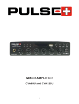
MX-120M
MIXER AMPLIFIER WITH AUDIO SOURCES
Please follow the instructions in this manual to obtain the optimum
results from this unit.
We also recommend that you keep this manual handy for future reference
Check our website for any updates of this manual: www.artsound.be
House of Music nv
Ronse, Belgium
www.artsound.be
Tel. +32 9 380 81 80
Fax. +32 9 386 12 35

MX-120M
2
Table of contents
1. Safety precautions 3
2. General description 4
3. Features 4
4. Nomenclature and functions 5
4.1 front panel 5
4.2 Remote control 5
4.3 rear panel 6
5. Operation illustration 6
6. Troubleshooting 8
7. Specications 8
8. Applications 9
9. Block diagram 10
10. Dimensional diagram 11

MX-120M
3
1 Safety precautions.
• Be sure to read the instructions in this section carefully before use.
• Make sure to observe the instructions in this manual as the conventions of safety symbols and messages regarded
as very important precautions are included.
• We also recommend you keep this instruction manual handy for future reference.
Warnings and safety.
Safety Symbol and Message Conventions.
Safety symbols and messages described below are used in this manual to prevent bodily injury and property damage,
which could result from mishandling. Before operating your product, read this manual rst and understand the safety
symbols and messages so you are thoroughly aware of the potential safety risk.
Warning.
When Installing the Unit.
• Do not expose the unit to rain or an environment
where it may be splashed by water or other liquids, as
doing so may result in re or electric shock.
• Use the unit only with the voltage specied on the unit.
Using a voltage higher than that which is specied may
result in re or electric shock.
• Do not cut, kink, otherwise damage nor modify the
power supply cord. In addition, avoid using the power
cord in close proximity to heaters, and never place
heavy objects -- including the unit itself -- on the pow-
er cord, as doing so may result in re or electric shock.
• Be sure to replace the unit’s terminal cover after
connection completion. Because high voltage is applied
to the speaker terminals, never touch these terminals
to avoid electric shock.
• Be sure to ground to the safety ground (earth) terminal
to avoid electric shock. Never ground to a gas pipe as a
catastrophic disaster may result.
• Avoid installing or mounting the unit in unstable
locations, such as on a rickety table or a slanted
surface. Doing so may result in the unit falling down,
causing personal injury and/or property damage.
WARNING
Indicates a potentially hazardous situation which, if mishandled, could result in death or serious
personal injury.
CAUTION
Indicates a potentially hazardous situation which, if mishandled, could result in moderate or
minor personal injury, and/or property damage.
When the Unit is in Use.
• Should the following irregularity be found during use,
immediately switch off the power, disconnect the power
supply plug from the AC outlet and contact your near-
est ArtSound dealer. Make no further attempt to oper-
ate the unit in this condition as this may cause re or
electric shock.
• If you detect smoke or a strange smell coming from
the unit.
• If water or any metallic object gets int o the unit
• If the unit falls, or the unit case breaks
• If the power supply cord is damaged (exposure of
the core, disconnection, etc.)
• If it is malfunctioning (no tone sounds.)
• To prevent a re or electric shock, never open nor
remove the unit case as there are high voltage compo-
nents inside the unit. Refer all servicing to your nearest
ArtSound dealer.
• Do not place cups, bowls, or other containers of liquid
or metallic objects on top of the unit. If they acciden-
tally spill into the unit, this may cause a re or electric
shock.
• Do not insert nor drop metallic objects or ammable
materials in the ventilation slots of the unit’s cover, as
this may result in re or electric shock.

MX-120M
4
2. General description.
3. Features
This product is a mixer amplier with Bluetooth radio, adopting by combination of high-performance switching power
supply and digital power amplier, with 1U chassis design, high efciency, light weight & delicate appearance.
• With 1U chassis design, internal combination of switch-
ing power supply and digital power amplier higher
efciency, light weight and delicate appearance.
• MP3 decoding module supports automatic switching of
USB/SD/Bluetooth/FM playback, congure MP3 remote
control; support power-off memory function, MIC re-
cording function.
• Support 1 channel EMC input, 2 channels AUX input, 4
channels MIC input.
• Each input has independent volume adjustment with
treble, bass, and volume control.
• The equipment is equipped with level indication, over-
load and protection indicator, and has good protection
for short circuit, overload and overheat situation.
• With mute function, microphone input, microphone is
prior to line input; mute function, MIC1 is prior to other
audio inputs, EMC takes precedence over all audio
inputs.
• Channel priority function: EMC>MIC1>MIC2/MIC3/
MIC4/AUX1/AUX2/MP3.
• Adopt advanced and high-efciency power amplify
circuit, the speaker output is 100V or 4 ohms; rated
output power is 120W.
• Input AC power, power supply 180W.
• It is forced to air-cool from front to the rear, and it
rotates at a constant speed when starting up. It speeds
up as the temperature rises and can work for a long
time.
When the Unit is in Use.
Caution.
When Installing the Unit.
An all-pole mains switch with a contact separation of at least 3 mm in each pole shall be incorporated in
the electrical installation of the building.
Due to product upgrades, while some of the features and specication in the user manual does not
match the actual functions, sorry for any inconvenience and thanks for your kind understanding!
• Never plug in nor remove the power supply plug with
wet hands, as doing so may cause electric shock.
• When unplugging the power supply cord, be sure to
grasp the power supply plug; never pull on the cord
itself. Operating the unit with a damaged power supply
cord may cause a re or electric shock.
• When moving the unit, be sure to remove its power
supply cord from the wall outlet. Moving the unit with
the power cord connected to the outlet may cause
damage to the power cord, resulting in re or electric
shock. When removing the power cord, be sure to hold
its plug to pull.
• Do not block the ventilation slots in the unit’s cover.
Doing so may cause heat to build up inside the unit and
result in re.
• Avoid installing the unit in humid or dusty locations,
in locations exposed to the direct sunlight, near the
heaters, or in locations generating sooty smoke or
steam as doing otherwise may result in re or electric
shock.
• Do not place heavy objects on the unit as this may
cause it to fall or break which may result in personal
injury and/or property damage. In addition, the object
itself may fall off and cause injury and/or damage.
• Make sure that the volume control is set to minimum
position before power is switched on.
• Loud noise produced at high volume when power is
switched on can impair hearing.
• Do not operate the unit for an extended period of time
with the sound distorting. This is an indication of a
malfunction, which in turn can cause heat to generate
and result in a re.
• Contact your ArtSound dealer as to the cleaning. If
dust is allowed to accumulate in the unit over a long
period of time, a re or damage to the unit may result.
• If dust accumulates on the power supply plug or in the
wall AC outlet, a re may result. Clean it periodically.
In addition, insert the plug in the wall outlet securely.
• Switch off the power, and unplug the power supply plug
from the AC outlet for safety purposes when cleaning
or leaving the unit unused for 10 days or more. Doing
otherwise may cause a re or electric shock.

MX-120M
5
ON
OFF
POWER
MIC1 INP UT
MX-120M
PROT
A UX 2MIC 3
MIC 1
MIC 2 MA STER
100V
SIG
CLIP
TREBLEBA S S
10 0 10 0 10 0 10 0 10 0 10 0
4-16
Ω
MIC /4 A UX 1
/
/
//
TFUSB
IR
16 17
1
4
1920
6 7 8 9 10 11
12
13 14
15
5
2
3
21
18
MOD E
E Q
S T OP
1
2
3
4
5
6
7
8
910
4. Nomenclature and functions.
4.1 Front panel
1. Record button
2. Repeated button
3. Playback / Pause
4. Next / volume reduce
5. USB interface
6. MIC1 unbalanced input jack
7. MIC1 volume control knob
8. MIC2 volume control knob
9. MIC3 volume control knob
10. MIC4 / AUX1 volume control knob
11. AUX2 volume control knob
12. BASS adjustment potentiometer
13. TREBLE adjustment potentiometer
14. Master volume control
15. PROT/100V/4-16Ω/CLIP/SIG
status indicators
16. The power switch
17. The power indicator
18. SD / MMC card slot
19. PREV /volume plus
20. LED display
21. MP3 mode selection
1. Power switch
2. Mode
3. Previous/next
4. Volume increase/decrease
5. 0~9 number button
6. Play/pause
7. Sound effect control
8. Mute
9. Cycle play button
10. Pause
Normal usage distance of remote control:
Remote control distance: 8 meter, angle: level ±35, vertical ±15.
Remote control usage attention:
1. When install battery, please mind electrode.
2. Please let remote control aim right with window of host machine.
3. When found remote distance get short and insensitive, please change battery.
4. Please take out battery when don’t use it for a long time.
5. Take it easy in case of falling.
4.2 Remote control

MX-120M
6
OUTPUT
4-16Ω100V
MUTE
AUDIO AUX2 AUX1
OUTPUT INPUT
MIC
LINE
PHANTOM
MIC
LINE
PHANTOM
MIC
LINE
PHANTOM
MIC
LINE
PHANTOM
MIC 4 MIC 3 MIC 2
EMC IN
MUTE
G G G
G
+
MIC 1
FM ANT
G
100V/4-16Ω
NC NC
1
2
3 5 7
4
15
6
8 9
1011
12
13
14
16
17
18
4-16Ω100V
OUTPUT
100V/4-16Ω
NC NC
SPK -
SPK +
4-16Ω100V
OUTPUT
100V/4-16Ω
NC NC
SPK -
SPK +
4-16Ω100V
OUTPUT
100V/4-16Ω
NC NC
SPK -
SPK +
4-16Ω100V
OUTPUT
100V/4-16Ω
NC NC
SPK -
SPK +
1. AC power input socket
2. 100V/4-16 Ω output interface
3. 100V / 4-16Ω speaker output switch
4. Cooling fan
5. Line output interface, used to connect the line input
interface
6. 2 channel AUX input interface, used to connect AUX
output interface
7. Line input /Mic input /Phantom power switch for
MIC4
8. MIC4/AUX1 Balance input
9. Line input /Mic input /Phantom power switch for MIC3
10. MIC3 Balance input
11. Line input /Mic input /Phantom power switch for
MIC2
12. MIC2 Balance input
13. MUTE control switch
14. Line input /Mic input /Phantom power switch for
MIC1
15. EMC input interface
16. MUTE signal input port
17. FM radio antenna interface
18. MIC1 Balance input
4.3 Rear panel.
NOTE
• Before connecting the speakers, please make sure that the equipment is powered off. In the
case of power on, may have the risk of electric shock.
• Please make sure there are no applied load to the speaker cables.
• During the installation of speakers, please make sure that the sum of the rated input power of
the speakers to be connected is less than rated power of equipment.
5. Operation illustration.
1 Connect the speakers
2 Connect external devices
• Please ensure that the equipment and all equipment will be connected are powered off.
• Using the corresponding cable to connect this equipment and other external equipment.
• When the 100V and 4-16Ω selector switch to 100V
position, as shown below:
Constant pressure speaker:
According to the rated
power of the power ampli-
er, connect the constant
power speaker.
• When the 100V and 4-16Ω selector switch to 4-16Ω
position, as shown below:
Fixed resistance speaker:
4-16Ω

MX-120M
7
NOTE
• Before powering on, please check and make sure there is no problem with the cable and con-
nection.
• When you turn off the system, turn off the equipment, and then turn off the connected equip-
ment.
NOTE
• Turn off the power switch,Please wait about 5 seconds before turning on again. Continuous
rapid turning on and off the power switch, it will lead to equipment failure.
• Even the switch is in the off status, there will be a little current in equipment. If it won’t use
the equipment in a long time, please unplug the power cord from the wall AC socket.
• When using the built-in MP3 player buttons, please pay attention the strength when control,
avoid excessive force to cause damage of MP3 player button.
• When insert SD card or USB interface. Please insert in a right way, avoid the wrong way or too
hard to cause the damage of the SD card or USB interface.
3 Connect the power line and turn it on:
• Please make sure that the power switch of equipment and its connected equipment are turned off (in the OFF posi-
tion).
• Turn the volume knob to the left
• Connect the supplied power line to the AC IN interface
• Plug the power line into the applicable socket
• Turn on the connected equipment (CD player, etc.), and then turn on the equipment.
4 Use of microphone
• Turning the volume knob to the left,Connect the microphone and microphone input interface.
• Turning the volume knob in the right position.
• Facing the microphone and Speak loudly, turn the volume knob to the right, until the output signal no longer distor-
tion. If input is high but output is low voice, and then increase the volume by using the volume knob. If the speaker
volume is very high, then reduce the volume by using the volume knob.
5 Shutdown the system
• Turning the volume knob to the left until the minimum position.
• Turning off the panel power switch of the professional power amplier, at 0ff.In turn shutoff processor equipment
and audio source equipment.
6 Built-in MP3 player operation method:
• USB and SD card interface with functions of “priority to
automatically play audio”.
• MODE”button: press the “MODE”: choose radio, bluetooth or audio playback.
• button : if press quickly, it is last song; Long press is the volume decrease.
• button: when playing music, press one time quickly is pause,press again
is play.
• button: if press quickly, it is next song; Long press is the volume increase.
• button: Long press; record audio signal from microphone.
7 Operating method of Bluetooth of Mobile phone:
• Press the “MODE” button on the MP3 player to select the setting to Bluetooth mode.
• Enter the settings of your phone and nd the relevant settings for Bluetooth.
• Tap the Bluetooth switch to turn it on. If it is already on, you can ignore it. The setup interface may vary slightly
from different phone systems.
• Note that after the phone Bluetooth is turned on, the search for the Bluetooth paired phone must be set to allow all
devices to detect, otherwise the search pairing may not be completed.
• After searching for the MX-120M device, click on the searched MX-120M device, it will automatically connect and
pair. After the pairing is completed, the phone music could be played normally.

MX-120M
8
7.Specications.
Model MX-120M
Rated Power 120W
Output Level 4-16Ω/100V
Input sensitivity MIC1,2,3,4 input:5mV±1mV/600Ω, balanced European terminal;
AUX1,2 input:350mV±20mV/10KΩ, unbalanced RCA connection terminal;
EMC input:775mV±40mV/10K balanced European terminal
Output Sensitivity& Impedance MIX OUT: 1000mV/470Ω
unbalanced RCA connection terminal
Tones Bass:±10dB at 100Hz
Treble:±10dB at 10KHz
High frequency:±10dB at 10KHz
Frequency response 80Hz~16KHz(+1dB,-3dB)
Signal-to-noise ratio MIC: ≥65dB; Music:≥70dB
Cross talk attenuation ≥50dB
SNR S/N Ratio MIC1,2,3:66dB / AUX1, 2:85dB
THD ≤0.05%(at 1KHz, 1/3 rated power)
Indicator Power indicator
Cooling Mode Forced fan to cool after side entry, boot to start the fan, and do the vari-
able speed processing innitely.
Protection Mode Overheat protection, overcurrent protection, short circuit protection
Operation Temperature +5°C~+40°C
Storage Temperature -20°C~+70°C
Relative Humidity <95%(No condensation)
Voltage ~230V 50Hz
Power consumption 180W
Weight 4.7Kg
Dimensions 484×295×44mm
6. Troubleshooting
Failure phenomena Failure cause
1. Power switch is not opened • Power line is cut off
• The protection function of the equipment is not activated
2. All lines are connected, but
there is no sound.
• The power switch is not opened or the power plug is bad contacted.
• The fuse is burnt
• The volume knob is not opened or turned down to a extra low level
• There is no audio signal input
• There is short-circuit in the speaker line.
3. The sound suddenly disap-
pears in normal status.
• The equipment is in very high temperature to make it into protection status.
• The connection wire is bad contact.
4. Low sound • The equipment is set to be low impedance connection, but the speakers con-
nected is with high impedance.
5. The sound is distorted • The input level of Mic or external equipment is too high
8. The FM radio operation description:
First, connect the antenna that is packaged with the product to the “ANT” port on the rear panel of the machine
through the Phoenix terminal. The other end of the antenna is placed in an open space, such as the side window,
and then set the working mode of the MP3 module on the machine to FM mode. Search for stations and save them
automatically by pressing the play/pause button on the machine panel or on the remote control. After the automatic
search of the standby device is completed, select the station that you like to listen to by pressing the previous song or
the next song button on the machine panel or on the remote control.(Remarks: The machine has a power-off memory
function, and the FM frequency range is: 87.50-108.00MHz)

MX-120M
9
OUTPUT
4-16Ω100V
MUTE
AUDIO AUX2 AUX1
OUTPUT INPUT
MIC
LINE
PHANTOM
MIC
LINE
PHANTOM
MIC
LINE
PHANTOM
MIC
LINE
PHANTOM
MIC 4 MIC 3 MIC 2
EMC IN
MUTE
G G G
G
+
MIC 1
FM ANT
G
100V/4-16Ω
NC NC
OPEN
CL
OSE
PL A Y STOP NEXTPREVIOUS
ON
OFF
POWER
Audio source equipment like CD/MP3 player
M I C
VOL
P L AY
M
S
G
M
IC
in
P L A Y
SI R E N
RE C in
ON
OFF
ST ANDB Y
PL A YALARM MODE RECORD
S T O PST AR T
Alarm signal generator
Speaker
AC power input
8. Applications.
REAR PANEL CONNECTIONS

MX-120M
10
MIC1
MIC2
MIC3
MIC4
ENC IN
AUX2AUX1
2-STAGE EQ
BA SS TREBLE
LEVEL
MP3/BT MODLE
Protection circuit
LED display
Fun control
Amplifier output
LEVEL
LEVEL
LEVEL
LEVEL
LEVEL
MUTE_MIC1
MUTE_ALL
Q2
GND
MUTE_ALL
Q1
GND
MUTE_MIC1
AUDIO OUT
Switchover between and 100V4-16Ω
DC 24V inverter
power supply
switching
power supply
Amplifier
module
9. Block diagram.

MX-120M
11
Over 100
44
48
484
44
295
6
Over 100
Over 100
44
436
OUTPUT
4-16Ω100V
MUTE
AUDIO AUX2 AUX1
OUTPUT INPUT
MIC
LINE
PHANTOM
MIC
LINE
PHANTOM
MIC
LINE
PHANTOM
MIC
LINE
PHANTOM
MIC 4 MIC 3 MIC 2
EMC IN
MUTE
G G G
G
+
MIC 1
FM
ANT
G
100V/4-16Ω
NC NC
ON
OFF
POWER
MIC1 INPUT
MX-120M
PROT
AUX 2MIC 3
MIC 1
MIC 2 MASTER
100V
SIG
CLIP
TREBLEBASS
10 0 10 0 10 0 10 0 10 0 10 0
4-16
Ω
MIC /4 AUX 1
/
/
/
TFUSB
IR
ON
OFF
POWER
MIC1 INPUT
MX-120M
PROT
AUX 2MIC 3
MIC 1
MIC 2 MASTER
100V
SIG
CLIP
TREBLEBASS
10 0 10 0 10 0 10 0 10 0 10 0
4-16
Ω
MIC /4 AUX 1
/
/
/
TFUSB
IR
10. Dimensional diagram.
Keeptheunit’sallsidesover10cmawayfromobjectsthatmayobstructairowtopreventtheunit’s
internal temperature rise.
UNIT : mm
UNIT : mm

Discover the complete ArtSound
range at www.artsound.be
K www.artsound.be
E Artsound.audio
Q artsoundaudio
/