Page is loading ...

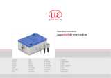
Instruction Manual
IF1032/ETH

MICRO-EPSILON
MESSTECHNIK
GmbH & Co. KG
Königbacher Straße 15
94496 Ortenburg / Germany
Tel. +49 (0) 8542 / 168-0
Fax +49 (0) 8542 / 168-90
e-mail [email protected]
www.micro-epsilon.com
Certified acc. to DIN EN ISO 9001: 2008
Interface Module

IF 1032/ETH
Contents
1. Safety ........................................................................................................................................ 7
1.1 Symbols Used ................................................................................................................................................. 7
1.2 Warnings .......................................................................................................................................................... 7
1.3 Notes on CE Identification ............................................................................................................................... 8
1.4 Proper Use ....................................................................................................................................................... 8
1.5 Proper Environment ......................................................................................................................................... 9
2. Functional Principle, Technical Data ..................................................................................... 10
2.1 Functional Principle ...................................................................................................................................... 10
2.2 Technical Data ............................................................................................................................................... 11
3. Delivery .................................................................................................................................. 12
3.1 Unpacking ..................................................................................................................................................... 12
3.2 Storage ......................................................................................................................................................... 12
4. Installation and Mounting ...................................................................................................... 13
4.1 Mounting the Interface Module ..................................................................................................................... 13
4.2 Pin Assignment Inputs and Outputs.............................................................................................................. 14
4.4 Power Supply ................................................................................................................................................. 16
4.5 RS485 Interface ............................................................................................................................................. 16
5. Operation ................................................................................................................................ 17
5.1 Configuring Sensor Interface......................................................................................................................... 17
5.2 Changing Data Rate ...................................................................................................................................... 17
5.3 Ethernet/EtherCAT Switching ........................................................................................................................ 18
5.4 Trigger Input ................................................................................................................................................... 19
5.5 Measuring Value Averaging ........................................................................................................................... 20
5.5.1 Introduction .................................................................................................................................. 20
5.5.2 Moving Average ............................................................................................................................ 20
5.5.3 Arithmetic Average ....................................................................................................................... 21
5.5.4 Median .......................................................................................................................................... 21
5.6 Synchronisation Output (only EtherCAT) ...................................................................................................... 21

IF1032/ETH
6. Ethernet Interface ................................................................................................................... 22
6.1 Hardware, Interface ....................................................................................................................................... 22
6.2 Data Format of Measuring Values ................................................................................................................. 27
6.2.1 Settings for Analog Inputs ............................................................................................................ 29
6.2.2 Settings for Sensors via RS485 .................................................................................................... 29
6.3 Commands .................................................................................................................................................... 29
6.3.1 Data Rate (STI = Set Sample Time) ............................................................................................ 30
6.3.2 Trigger Mode (TRG) ...................................................................................................................... 31
6.3.3 Filter, Averaging Type (AVT = Averaging Type) ........................................................................... 31
6.3.4 Filter, Averaging Number (AVN = Averaging Number) ............................................................... 32
6.3.5 Channel Status (CHS = Channel Status) .................................................................................... 32
6.3.6 Status (STS).................................................................................................................................. 32
6.3.7 Version (VER) ............................................................................................................................... 33
6.3.8 Ethernet Settings (IPS = IP-Settings) ........................................................................................... 33
6.3.9 Query Data Port (GDP = Get Data Port) ...................................................................................... 33
6.3.10 Set Data Port (SDP = Set Data Port) ........................................................................................... 34
6.3.11 Change between Ethernet and EtherCAT (IFC = Interface) ....................................................... 34
6.3.12 Access Channel Information (CHI = Channel info) ..................................................................... 35
6.3.13 Access Controller Information (COI = Controller info) ................................................................ 35
6.3.14 Login for Web Interface (LGI = Login) ......................................................................................... 35
6.3.15 Logout for Web Interface (LGO = Logout) .................................................................................. 36
6.3.16 Change Password (PWD = Password)........................................................................................ 36
6.3.17 Change Language for the Web Interface (LNG = Language) ..................................................... 36
6.3.18 Measuring Values Data Format (MDF = Measured Data Format) .............................................. 36
6.3.19 Set Sensor Interface (SIF = Sensor Interface) ............................................................................ 37
6.3.20 Sensor Baud Rate (SBR = Sensor Baud Rate) ........................................................................... 37
6.3.21 Sensor Address (SAD = Sensor Address) .................................................................................. 38
6.3.22 Analog Range (ARA) .................................................................................................................... 38
6.3.23 Sensor Search (SSE) ................................................................................................................... 38
6.3.24 Analog Offset (AOF) ..................................................................................................................... 39
6.3.25 Analog Unit (AUN) ........................................................................................................................ 39
6.3.26 Analog Math Function (AMF) ....................................................................................................... 40
6.3.27 Default Messages ......................................................................................................................... 40
6.4 Operation Using Ethernet .............................................................................................................................. 41
6.4.1 Requirements ............................................................................................................................... 41
6.4.2 Access via Web Interface ............................................................................................................. 43

IF 1032/ETH
6.5 Firmware Update ........................................................................................................................................... 43
6.6 Operating Menu, Set Interface Module Parameter ....................................................................................... 44
6.6.1 Preliminary Notes to the Settings ................................................................................................. 44
6.6.2 Menu Settings ............................................................................................................................... 45
6.6.2.1 Login, Changing User Level ........................................................................................ 45
6.6.2.2 Measuring Mode ......................................................................................................... 46
6.6.2.3 Trigger Mode ............................................................................................................... 47
6.6.2.4 Sensor Interface .......................................................................................................... 48
6.6.2.5 Digital Interfaces .......................................................................................................... 51
6.6.2.6 Manage Settings ......................................................................................................... 52
6.6.3 Menu Measuring ........................................................................................................................... 53
6.6.3.1 Channel Info ................................................................................................................ 53
6.6.3.2 Measuring Data Display .............................................................................................. 54
6.6.4 Menu Help, Info ............................................................................................................................ 56
7. EtherCAT Interface ................................................................................................................. 57
7.1 Introduction .................................................................................................................................................... 57
7.2 Change Interface ........................................................................................................................................... 58
8. Warranty .................................................................................................................................. 59
9. Service, Repair ...................................................................................................................... 59
10. Decommissioning, Disposal ................................................................................................. 60

IF1032/ETH
Appendix
A 1 Accessories ............................................................................................................................ 61
A 2 EtherCAT Documentation ...................................................................................................... 62
A 2.1 Preamble ........................................................................................................................................................ 62
A 2.1.1 Structure of EtherCAT® Frames .................................................................................................. 62
A 2.1.2 EtherCAT® Services ..................................................................................................................... 63
A 2.1.3 Addressing and FMMUs ............................................................................................................... 63
A 2.1.4 Sync Manager .............................................................................................................................. 64
A 2.1.5 EtherCAT State Machine .............................................................................................................. 65
A 2.1.6 CANopen via EtherCAT ................................................................................................................ 66
A 2.1.7 Process Data PDO-Mapping ........................................................................................................ 66
A 2.1.8 Service Data SDO Service ............................................................................................................ 66
A 2.2 CoE – Object Directory .................................................................................................................................. 67
A 2.2.1 Communication Specific Standard Objects (CiA DS-301) .......................................................... 67
A 2.2.2 Manufacturer Specific Objects ..................................................................................................... 70
A 2.3 Measurement Data Format ............................................................................................................................ 74
A 2.4 EtherCAT Configuration with the Beckhoff TwinCAT©-Manager .................................................................. 75

Page 7
Safety
IF1032/ETH
1. Safety
The handling of the system assumes knowledge of the instruction manual.
1.1 Symbols Used
The following symbols are used in the instruction manual.
Indicates a hazardous situation which, if not avoided, may result in minor or moder-
ate injuries.
Indicates a situation which, if not avoided, may lead to property damage.
Indicates a user action.
i
Indicates a user tip.
Measure
Indicates a hardware or a button/menu in the software.
1.2 Warnings
Connect the power supply and the display / output device in accordance with the safety regulations for elec-
trical equipment.
> Danger of injury
> Damage to or destruction of the interface module
The power supply must not exceed the specified limits.
> Damage to or destruction of the interface module
Avoid shock and vibration to the interface module.
> Damage to or destruction of the interface module
Avoid continuous exposure to fluids on the interface module.
> Damage to or destruction of the interface module

Page 8
Safety
IF1032/ETH
1.3 Notes on CE Identification
The following applies to the interface module IF1032/ETH:
- EU directive 2004/108/EC
1
- EU directive 2011/65/EC, “RoHS“ category 11
Products which carry the CE mark satisfy the requirements of the quoted directives and the European
standards (EN) listed therein. The EC declaration of conformity is kept available according to EC regulation,
article 10 by the authorities responsible at
MICRO-EPSILON MESSTECHNIK
GmbH & Co. KG
Königbacher Straße 15
94496 Ortenburg / Germany
The interface module IF1032/ETH is designed for use in industry and satisfies the requirements.
1) EMC
1.4 Proper Use
- The interface module IF1032/ETH is designed for use in industrial and laboratory areas. It is used to con-
vert the MICRO-EPSILON internal sensor protocol (RS485) to Ethernet or EtherCAT.
- The interface module may only be operated within the limits specified in the technical data, see Chap. 2.2.
- Use the IF1032/ETH in such a way that in case of malfunctions or failure personnel or machinery are not
endangered.
- Take additional precautions for safety and damage prevention for safety-related applications.

Page 9
Safety
IF1032/ETH
1.5 Proper Environment
- Protection class: IP 40
- Operating temperature: 0 ... +60 °C (+32 ... +140 °F)
- Storage temperature: -10 ... +75 °C (+14 ... +167 °F)
- Humidity: 5 - 95 % (non-condensing)
- Ambient pressure: Atmospheric pressure

Page 10
Functional Principle, Technical Data
IF1032/ETH
2. Functional Principle, Technical Data
2.1 Functional Principle
The IF1032/ETH interface module is used for conversion of the MICRO-EPSILON internal sensor protocol
(RS485) to Ethernet or EtherCAT. The IF1032/ETH interface module also has three analog inputs (2 x 0 -10 V
voltage, 1 x 4 - 20 mA current) which can be used to convert the measuring values from analog sensors to
Ethernet/EtherCAT.
Features:
- Automatic detection of MICRO-EPSILON sensors which support the MICRO-EPSILON internal sensor
protocol via RS485
- Alternatively three analog inputs with configurable sampling frequency from 2 Sps – 4 kSps and trigger
function
- Ethernet interface
- EtherCAT interface

Page 11
Functional Principle, Technical Data
IF1032/ETH
2.2 Technical Data
Model IF1032/ETH
Power supply +5 ... +36 V
Power consumption (without sensor) approx. 1.2 W
Inputs RS485 (ME protocol)
3 analog inputs (2 x voltage, 1 x current)
Trigger input (only for analog inputs)
Outputs Ethernet, EtherCAT, Sync output (only EtherCAT)
Analog inputs Measuring range 2 x 0 - 10 V voltage (max. 20 V!);
1 x 4 - 20 mA current (max. 30 mA!)
Resolution 14 Bit
Linearity
±0.1 %
Sampling rate 2 Sps - 4 kSps
Temperature stability 30 ppm
RS485 interface Baud rate: 9200 - 6250000
Only sensors with ME sensor protocol
EtherCAT min. cycle time approx. 500 μs
Operating temperature 0 ... +60 °C (+32 ... +140 °F)
Storage temperature -10 ... +75 °C (+14 ... +167 °F)
Protection class IP 40

Page 12
Delivery
IF1032/ETH
3. Delivery
3.1 Unpacking
1 IF1032/ETH interface module
1 Ethernet cable, 3 m long
1 Instruction Manual
1 CD with measurement tool MEDAQ-LIB (Ethernet), SensorFinder, ESI-File (EtherCAT)
2 Terminal blocks
Check for completeness and shipping damage immediately after unpacking.
In case of damage or missing parts, please contact the manufacturer or supplier.
3.2 Storage
Storage temperature: -10 ... +75 °C (+14 ... +167 °F)
Humidity: 5 - 95 % (non-condensing)

Page 13
Installation and Mounting
IF1032/ETH
4. Installation and Mounting
i
Pay attention to careful handling during mounting and operation.
4.1 Mounting the Interface Module
25
(.98)
69 (2.72)
84 (3.31)
2 (.08)
55.4 (2.18)
10 (.39)
4 (.16)
(2x) ø 4.2
(.17 dia.)
(2x) 4.2 (.17)
6.5 (.26)
59.2 (2.33)
11 (.43)
10
(.39)
53 (2.09)
103.5 (4.07)
110 (4.33)
42 (1.65)
5.8 (.23)
16
(.63)
Fig. 1 Dimensional drawing IF1032/ETH, dimensions in mm, not to scale

Page 14
Installation and Mounting
IF1032/ETH
4.2 Pin Assignment Inputs and Outputs
Connect the inputs V+ and GND to a power supply.
The power supply must correspond to that of the connected sensor as it is internally looped through to the
sensor.
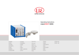
MICRO-EPSILON recommends the use of the optionally available power supply PS2020 or the plug-in power
supply PS2401 for the interface module, see Fig. 2., input
100 - 240 VAC, output 24 VDC/2.5 A, see Chap. A
1.
L1
+
+
N
PS2020
230 VAC
PE
Fig. 2 Interface module with optional power supply PS2020

Page 15
Installation and Mounting
IF1032/ETH
Supply socket (left)
V+ Positive power supply (5 - 36 V)
GND Power supply ground
V- Negative power supply (if required by sensor)
TRG IN+
Trigger input + (LVDS signal, max. 3.3 V, only for analog inputs)
TRG IN- Trigger input - (LVDS signal, max. 3.3 V, only for analog inputs)
Sensor socket (right)
V+ Positive power supply for sensor (looped through)
GND Power supply ground for sensor (looped through)
V- Negative power supply for sensor (looped through)
RS485 A RS485 sensor interface (only ME sensor protocol)
RS485 B RS485 sensor interface (only ME sensor protocol)
U1 IN
Voltage input 1 for AD converter (0 - 10 V) (= CH1)
I1 IN Current input 1 for AD converter (4 - 20 mA) (= CH3)
GND 1 Ground for voltage-, current input
U2 IN
Voltage input 2 for AD converter (0 - 10 V) (= CH2)
GND 2 Ground for voltage, current input
SY OUT+ Synchronisation output + (= EtherCAT distributed clocks, LVDS signal)
SY OUT - Synchronisation output - (= EtherCAT distributed clocks, LVDS signal)

Page 16
Installation and Mounting
IF1032/ETH
4.4 Power Supply
The power supply is looped through from the supply socket to the sensor socket, i.e. the power supply must
match that of the sensor. The positive voltage must be between 5 V and 36 V. The negative supply voltage
is not needed by the IF1032/ETH, but is only looped through for the sensor in case this needs an additional
negative voltage.
4.5 RS485 Interface
i
Look for a RS485 bus to a correct line termination!
We recommend a termination resistance of 120 Ohm between RS485 A and RS485 B both at the bus start
and end. The IF1032/ETH is a RS485 master; internally a termination resistance of 120 Ohm is permanently
attached. The IF1032/ETH should be at the bus start. In short RS485 lines (< 5 m) or low baud rates can usu-
ally be waived on a termination resistance at the end of the bus.

Page 17
Operation
IF1032/ETH
5. Operation
5.1 Configuring Sensor Interface
Either a sensor supporting the ME sensor protocol can be connected via RS485 or alternatively the analog
inputs of the interface module can be used.
For this it is necessary to select the appropriate sensor port in the interface module using the web interface
(alternatively via Ethernet commands or using CoE for EtherCAT).
For RS485, the baud rate and address of the sensor must also be set. All characteristics of the sensor (e.g.
name, measuring range, possible filter types, ...) are then automatically retrieved from the sensor.
If the analog inputs are selected as sensor interface, the measuring range, offset and the unit per input can
be defined in the web interface for the scaling of the measuring values. Thus, only changes the scaling of the
measuring values; the actual input voltage range and/or input current range does not change as a result.
5.2 Changing Data Rate
Any sampling frequency between 2 Sps and 4 kSps can be set for the analogue inputs.
Use the web interface or the appropriate Ethernet command for this.
If a sensor is connected via RS485, the possible data rates are dependent on the connected sensor.
Write the required data rate for this, e.g. in the web interface.
After confirmation, the nearest possible data rate is set in the sensor and displayed in the web interface.

Page 18
Operation
IF1032/ETH
5.3 Ethernet/EtherCAT Switching
Switching between Ethernet and EtherCAT can either be performed using the hardware switch, see Fig. 3, or
by software.
Fig. 3 Switch for changing the interface
If the switch is in the Ethernet position, the Ethernet interface is always active irrespective of the software
setting. If the switch is in the ECAT/Auto position, the interface set by the software is active. Any change of
the interface does not come into effect until after restart of the interface module.

Page 19
Operation
IF1032/ETH
5.4 Trigger Input
The trigger input is only for the analog inputs of the IF1032/ETH. If the sensor to be connected has a trigger
input itself, this must be used.
Use an LVDS signal with max. 3.3 V for the trigger input.
Activate the trigger mode and set a data rate which is larger than the maximum trigger frequency.
There are three possible settings for the trigger input:
Trigger mode 1 (rising edge)
A measuring value is sent for each rising edge at the trigger input. The specified data rate must be greater
than the maximum trigger frequency. If triggering is faster than the specified data rate, separate measuring
values are sent duplicated as new measuring values of the AD converter are not yet present internally.
Trigger mode 2 (high level)
The measuring values are sent with the specified data rate while a logical High level is present at the trigger
input.
Trigger mode 3 (gate rising edge)
With the first rising edge at the trigger input, the interface module starts sending the measuring values with
the specified data rate; it stops sending measuring values with the second rising edge and so on …
i
If a sensor is connected via RS485, the trigger input of the sensor (if present) must be used.
The supported trigger modes are dependent on the sensor.

Page 20
Operation
IF1032/ETH
5.5 Measuring Value Averaging
5.5.1 Introduction
The measuring value averaging is performed before the output of the measuring values via the Ethernet inter-
faces. The averaging types are dependent on the connected sensor. Not all sensors support every averaging
type.
Due to the measuring value averaging, the resolution is improved, individual interference points are hidden or
the measurement result is “smoothed”.
i
The linearity is not influenced by averaging. The averaging has no influence on the data rate.
The interface module is shipped from the factory without averaging.
5.5.2 Moving Average
The selected number N of successive measuring values (window width) is used to generate the arithmetic
average M
gl
on the basis of the following formula:
MV (k)
k=1
N
N
M =
gl
∑
MW = Measuring value
N = Number
k = Running index
M
gl
= Averaging value
Fig. 4 Formula for moving average
Mode
Each new measuring value is added and the first (oldest) measuring value from the averaging process is
taken out again.
Example with N = 7:
.... 0 1 2 3 4 5 6 7 8
gets to
2+3+4+5+6+7+8
7
averaging value n
.... 1 2 3 4 5 6 7 8 9
gets to
3+4+5+6+7+8+9
7
averaging value n +1
/