MICRO-EPSILON capaNCDT 6110/6120/IP User manual

Type
User manual
CSE05
CSE1
CSE1,25
CSE2
CSE3
CSE05/M8
CSE1,25/M12
CSE2/M16
CSE3/M24
CSF2
CSF4
CSF6
CSF2-CRg4,0
CSF4-CRg4,0
CSF6-CRg4,0
Operating Instructions
capaNCDT 6110/6120/IP
MICRO-EPSILON
MESSTECHNIK
GmbH & Co. KG
Königbacher Straße 15
94496 Ortenburg / Germany
Tel. +49 (0) 8542 / 168-0
Fax +49 (0) 8542 / 168-90
www.micro-epsilon.com
Non-contact Capacitive Displacement Measuring
capaNCDT 61xx/IP
Contents
1. Safety ........................................................................................................................................ 5
1.1 Symbols Used ................................................................................................................................................. 5
1.2 Warnings .......................................................................................................................................................... 5
1.3 Notes on CE Marking ...................................................................................................................................... 6
1.4 Intended Use ................................................................................................................................................... 7
1.5 Proper Environment ......................................................................................................................................... 7
2. Functional Principle, Technical Data ...................................................................................... 8
2.1 Measuring Principle ......................................................................................................................................... 8
2.2 Structure .......................................................................................................................................................... 9
2.2.1 Sensors ........................................................................................................................................ 11
2.2.2 Sensor Cable................................................................................................................................ 12
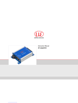
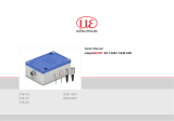
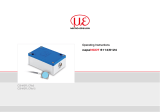
2.2.3 Controller ...................................................................................................................................... 13
2.3 Technical Data ............................................................................................................................................... 14
3. Delivery .................................................................................................................................. 15
3.1 Unpacking ...................................................................................................................................................... 15
3.2 Storage .......................................................................................................................................................... 15
4. Installation and Assembly ...................................................................................................... 16
4.1 Precautionary Measures ................................................................................................................................ 16
4.2 Sensor ............................................................................................................................................................ 16
4.2.1 Radial Point Clamping, Circumferential Clamping, Series CSE Sensors ................................... 16
4.2.2 Mounting with Thread, Series CSEx/Mx Sensors ........................................................................ 17
4.2.3 Dimensional Drawings Sensors ................................................................................................... 18
4.3 Sensor Cable ................................................................................................................................................. 22
4.3.1 General ......................................................................................................................................... 22
4.3.2 Cable with Type C Connector ...................................................................................................... 22
4.3.3 Cable with Type B Connector ...................................................................................................... 24
4.3.4 Cable with Type E Connector ...................................................................................................... 26
4.4 Controller ....................................................................................................................................................... 27
4.5 Ground Connection, Grounding.................................................................................................................... 28
4.6 Power Supply, Display/Output Device, Sensor Connection ......................................................................... 28
capaNCDT 61xx/IP
5. RS485 Interface ...................................................................................................................... 29
5.1 Hardware Interface ........................................................................................................................................ 29
5.2 Protocol .......................................................................................................................................................... 29
5.2.1 Reading Measuring Values .......................................................................................................... 30
5.2.2 Scaling the Measuring Values ..................................................................................................... 31
5.2.3 Example of the Measuring Value Transmission ........................................................................... 32
5.2.4 Setting the RS485 Address .......................................................................................................... 34
5.3 Commands and Settings ............................................................................................................................... 35
6. Operation ................................................................................................................................ 36
7. Maintenance ........................................................................................................................... 37
8. Liability for Material Defects .................................................................................................. 38
9. Decommissioning, Disposal .................................................................................................. 38
Appendix
Seite 5
Safety
capaNCDT 61xx/IP
1. Safety
Knowledge of the operating instructions is a prerequisite for equipment operation.
1.1 Symbols Used
The following symbols are used in this instruction manual:
Indicates a hazardous situation which, if not avoided, may result in minor or moder-
ate injury.
Indicates a situation that may result in property damage if not avoided.
Indicates a user action.
i
Indicates a tip for users.
1.2 Warnings
Disconnect the power supply before touching the sensor surface.
> Risk of injury
> Static discharge
Connect the power supply and the display/output device in accordance with the safety regulations for electri-
cal equipment.
> Risk of injury
> Damage to or destruction of the sensor and/or controller
Avoid shocks and impacts to the sensor and controller.
> Damage to or destruction of the sensor and/or controller
The power supply must not exceed or continuously fall below the specified limits.
> Damage to or destruction of the sensor and/or controller
Seite 6
Safety
capaNCDT 61xx/IP
Protect the sensor cable against damage
> Destruction of the sensor
> Failure of the measuring device
1.3 Notes on CE Marking
The following apply to the capaNCDT 61x0/IP:
- EU directive 2014/30/EU
- EU directive 2011/65/EU, “RoHS“ category 9
Products which carry the CE mark satisfy the requirements of the EU directives cited and the European
harmonized standards (EN) listed therein. The EU Declaration of Conformity is available to the responsible
authorities according to EU Directive, article 10, at:
MICRO-EPSILON Messtechnik GmbH & Co. KG
Königbacher Straße 15
94496 Ortenburg / Germany
The measuring system is designed for use in industrial environments and meets the requirements.
.
Seite 7
Safety
capaNCDT 61xx/IP
1.4 Intended Use
- The capaNCDT 61x0/IP measuring system is designed for use in industrial areas. It is used for
displacement, distance, thickness and movement measurement
position measuring of parts or machine components
- The system must only be operated within the limits specified in the technical data, see Chap. 2.3.
The system must be used in such a way that no persons are endangered or machines and other materi-
al goods are damaged in the event of malfunction or total failure of the system.
Take additional precautions for safety and damage prevention in case of safety-related applications.
1.5 Proper Environment
- Protection class:
Sensor IP 40, IP 54 (functionality reduced)
Controller IP 68
- Operating temperature:
Sensor: -50 ... +200 °C (-58 to +392 °F), type CSE
-40 ... +100 °C (-40 to 212 °F), type CSF
Sensor cable: -20 ... +80 °C (-4 to 176 °F) (permanently)
-20 ... +100 °C (-4 to 212 °F) (up to 10,000 h)
Controller: -20 ... +60 °C (-4 to 140 °F)
- Humidity: 5 - 95 % (non-condensing)
- Ambient pressure: Atmospheric pressure
- Storage temperature:
Sensor: -50 ... +200 °C (-58 to +392 °F), type CSE
-40 ... +100 °C (-40 to 212 °F), type CSF
Sensor cable: -50 ... +80 °C (-58 to 176 °F)
Controller: -20 ... +75 °C (-4 to 167 °F)
- The space between the sensor surface and the target must have an unvarying dielectric constant.
- The space between the sensor surface and the target may not be contaminated (for example water,
rubbed-off parts, dust, etc.).
Seite 8
Functional Principle, Technical Data
capaNCDT 61xx/IP
2. Functional Principle, Technical Data
2.1 Measuring Principle
The principle of capacitive distance measurement with the capaNCDT system is based on the principle of the
parallel plate capacitor. For conductive targets, the sensor and the target opposite form the two plate elec-
trodes.
If a constant AC current flows through the sensor capacitor, the amplitude of the AC voltage at the sensor is
proportional to the distance between the capacitor electrodes. The AC voltage is demodulated, amplified and
output as an analog signal.
The capaNCDT system evaluates the reactance X
C
of the plate capacitor which changes strictly in proportion
to the distance:
X = ; capacitance C = * *
c
1
jC
area
distance
r
o
i
A small target and bent (uneven) surfaces cause a non-linear characteristic.
This theoretical relationship is realized almost ideally
in practice by designing the sensors as guard ring
capacitors.
The linear characteristic of the measuring signal is
achieved for electrically conductive target materials
(metals) without any additional electronic lineariza-
tion. Slight changes in the conductivity or magnetic
properties do not affect the sensitivity or linearity.
Electrical conductor
Ground
Screening electrode
Measuring electrode
Fig. 1 Functional principle of a capacitive sensor
Seite 9
Functional Principle, Technical Data
capaNCDT 61xx/IP
2.2 Structure
The non-contact, single-channel measuring system of capaNCDT 61xx/IP, installed in an aluminum housing,
consists of:
- Controller
- Sensor
- Sensor cable
- Power supply and signal cable
The signal processing electronics with oscillator, demodulator, AD converter and integrated preamplifier is in
the controller
1
.
6 pol. connector
Signal
f
OSZ
16 kHz
Oscillator
Demodulator
Preamplifier
Sensor
Sensor
cable
Voltage
processing
Fig. 2 Block diagram capaNCDT 6110/IP
1) The controller 6120/IP: Contains additionally an AD converter for converting to a RS485 interface.
Seite 10
Functional Principle, Technical Data
capaNCDT 61xx/IP
6 pol. connector
Signal
f
OSZ
16 kHz
Oscillator
Demodulator
Preamplifier
Sensor
Sensor
cable
Voltage
processing
A/D converter
Fig. 3 Block diagram capaNCDT 6120/IP
Sensor
10 V
5 V
0 V
Target
Measuring range (MR)
Displacement, mm
100 %0 % 50 %
0xF00000
0x0
RS485
1
20 mA
4 mA
Fig. 4 Glossary, signal output
1) Digital interface DT6120/IP/U, DT6120/IP/U/ECL2, DT6120/IP/I or DT6120/IP/I/ECL2 only.
Voltage or current output are only possible as an alternative.
Seite 11
Functional Principle, Technical Data
capaNCDT 61xx/IP
2.2.1 Sensors
For this measuring system, several sensors can be used.
Measuring
surface
sensor
Min. target
diameter
In order to obtain accurate measuring results, keep the surface of
the sensor clean and free from damage.
The capacitive measuring process is area-related. A minimum area, see
Fig. 5, is required depending on the sensor model and measuring range.
Sensor model Measuring range,
nominal
Min. target
diameter
CSE05 CSE05/M8 0.5 mm 6 mm
CSE1 1 mm 8 mm
CSE1,25 CSE1,25/M12 1.25 mm 10 mm
CSE2 CSE2/M16 2 mm 14 mm
CSE3 CSE3/M24 3 mm 20 mm
Sensor model
Measuring range,
nominal
Min. target
size
Min gap
width
CSF2 CSF2-CRg4,0 2 mm appr. 50.5 x 14.0 mm ≥ 0.75 mm
CSF4 CSF4-CRg4,0 4 mm appr. 90.5 x 17.5 mm ≥ 0.75 mm
CSF6 CSF6-CRg4,0 6 mm appr. 127.3 x 25 mm ≥ 0.75 mm
Fig. 5 Sensors for electrical conducting targets (metals)
Minimum
gap width
Measurement direction
Seite 12
Functional Principle, Technical Data
capaNCDT 61xx/IP
2.2.2 Sensor Cable
Sensor and controller are connected by a special, double screened sensor cable.
Do not shorten or lengthen these special cables.
Usually, a damaged cable can not be repaired.
Tread-proof model with metal hose is available for industrial applications.
Switch off the device when plugging and removing connectors.
Do not crush the sensor cable.
Do not modify to the sensor cable.
> Lost of functionality
Seite 13
Functional Principle, Technical Data
capaNCDT 61xx/IP
2.2.3 Controller
The capaNCDT 6110/6120/IP contains a voltage processing, oscillator, integrated preamplifier, demodulator
2
as well as an output level.
The voltage processing produces all necessary internal voltages from the power supply. The oscillator sup-
plies the sensor with frequency and amplitude-stabilized alternating voltage. The frequency is 16 kHz. The
internal preamplifier generates the distance-dependent measuring signal and amplifies it. Demodulator and
output level convert the measuring signal into a standard voltage signal
3
.
The output voltage can reach up to a maximum of 13 VDC when sensor is disconnected or measurement is
exceeded.
> Damage to downstream devices
Sensor
Supply/
Output
Fig. 6 Controller DT6110/6120/IP
2) The controller 6120: Contains additionally an AD converter.
3) An analog-digital converter converts the measuring signal and outputs it to the RS485 interface.
Seite 14
Functional Principle, Technical Data
capaNCDT 61xx/IP
2.3 Technical Data
Controller modell DT6110/IP/U DT6110/IP/I DT6120/IP/U DT6120/IP/I
Resolution static 0.01 % FSO (2 Hz)
Resolution dynamic 0.02 % FSO (1000 Hz)
Frequency response 1 kHz (-3 dB)
Linearity ≤ ±0.1 % FSO
Sensitivity ≤ ±0.1 % FSO
Long-term stability 0.02 % FSO/month
Temperature stability 50 ppm FSO/K (+10 … +40 °C); 100 ppm FSO/K (-20 … +10 °C and +40 … +60 °C)
Operating
temperature
Sensor type CSF -40 ... +100 °C | type CSE: -50 ... +200 °C
Sensor cable permanent: -20 ... +80 °C, up to 10,000 h: -20 ... +100 °C
Controller -20 … +60° C
Power supply
9 ... 28 VDC
(max. 1.4 W)
11 ... 28 VDC
(max. 2 W)
9 ... 28 VDC
(max. 1.6 W)
11 ... 28 VDC
(max. 2.2 W)
Output
analog
0 … 10 V
(short circuit proof)
optional: ±5 V, 10 … 0 V
4 … 20 mA
max. 500 Ohm load
0 … 10 V
(short circuit proof)
optional: ±5 V, 10 … 0 V
4 … 20 mA
max. 500 Ohm load
digital --- ---
RS485, 230400 Baud (adjustable),
24 bit measuring values, max. 2 kSamples (adjustable)
Storage temperature -20 ... +75 °C
Protection
class
Sensor IP 40, IP 54 (functionality reduced)
Controller IP 68
Shock 20 g / half sine 5 ms in XYZ axis / 1000 shocks per axis (DIN-EN 60068-2-29)
Vibration 10 g / 10 … 2000 Hz in XYZ axis / 10 cycles per axis (DIN-EN 60068-2-6)
Weight 165 g
FSO = Full Scale Output
Seite 15
Delivery
capaNCDT 61xx/IP
3. Delivery
3.1 Unpacking
1 Controller
1 Power supply and output cable SCAC3/6/IP
1 Instruction Manual
Optional accessories:
1 Sensor
1 Sensor cable with connector
1 IF1032/ETH interface converter from analog (DT6110/IP) or RS485 Ethernet (DT6120/IP) on
Ethernet/EtherCAT
You will find further optional accessories in the appendix.
Remove the parts of the system carefully from the packaging and transport them in such a way that they
are not damaged.
Check for completeness and shipping damages immediately after unpacking. In case of damage or
missing parts, please contact the manufacturer or supplier.
3.2 Storage
- Storage temperature:
Sensor: -50 ... +200 °C (-58 ... +392 °F)
Sensor cable: -50 ... +80 °C (-58 ... +176 °F)
Controller: -20 ... +75 °C (-4 ... +167 °F)
- Humidity: 5 - 95 % RH (non-condensing)
Seite 16
Installation and Assembly
capaNCDT 61xx/IP
4. Installation and Assembly
4.1 Precautionary Measures
No sharp-edged or heavy objects should be allowed to affect the sensor cable sheath.
Protect the cable against pressure loads in pressurized rooms.
Avoid folding the cables in any case.
Check the connections for tight fit.
i
A damaged cable cannot be repaired.
4.2 Sensor
The sensors may be mounted free-standing or ush.
When assembling, make sure that the polished sensor surface is not scratched.
4.2.1 Radial Point Clamping, Circumferential Clamping, Series CSE Sensors
Grub
screw
This simple type of fixture is only recommended for a
force and vibration-free installation position. The grub
screw must be made of plastic so that it cannot dam-
age or deform the sensor housing.
Fig. 7 Radial point clamping with grub screw
Do not use metal grub screws!
> Danger of damaging the sensor
Seite 17
Installation and Assembly
capaNCDT 61xx/IP
This sensor mounting option offers maximum reliability be-
cause the sensor is clamped around its cylindrical housing. It
is absolutely necessary in difficult installation environments,
for example on machines, production plants et cetera.
Fig. 8 Circumferential clamping with clamping ring
i
Tension at the cable is inadmissible!
4.2.2 Mounting with Thread, Series CSEx/Mx Sensors
For holders with an internal thread, a mounting nut is suffi-
cient for attaching the sensor. For thin holders, Micro-Epsilon
recommends mounting nuts on both sides for mounting.
Attach the sensor preferably at the end of the thread towards
the active measuring surface. Please note the maximum
torque, see Fig. 10.
Fig. 9 Mounting with thread
Active measuring surface sensor, connector side
Seite 18
Installation and Assembly
capaNCDT 61xx/IP
4.2.3 Dimensional Drawings Sensors
Cylindric sensors
CSE1CSE05 CSE1,25 CSE2 CSE3
24.0
(.94)
19.5
ø20.0h7
(.79 dia.)
ø19.2
(.76 dia.)
22.0
(.87)
18.5
ø14.0h7
(.55 dia.)
ø13.7
(.54 dia.)
22.0
(.87)
18.5
ø9.7
(.38 dia.)
ø10h7
(.39 dia.)
0.00
-0.20
ø8f7
(.31 dia.)
ø7.7
(.30 dia.)
12
(.47)
9.0
ø5.7
(.22 dia.)
ø6f7
(.24 dia.)
12
(.47)
9.0
Active measuring surface sensor, connector side
Dimensions in mm (inches), dimensional drawings of other sensors are available on request..
Seite 19
Installation and Assembly
capaNCDT 61xx/IP
CSE05/M8 CSE1,25/M12 CSE2/M16 CSE3/M24
14.0
17.0 (.67)
+0.1
-0.2
13.4 WS6
18.5
22.0 (.87)
17.6
18.5
22.0 (.87)
17.6
25.5
30.0 (1.18)
24.6
3.0
(.12)
ø5.7
ø6.0
(.24 dia.)
ø9.7
ø10
ø10.4 (.41 dia.)
M8x0.5
M12x1 M16x1
M24x1.5
4.0
(.16)
4.0
(.16)
5.0
(.20)
ø13.7
ø14.0
ø14.4 (.57 dia.)
ø19.2
ø20.0
ø20.6 (.81 dia.)
WS10
6.0
(.24)
10.0
(.39)
WS14
WS18
Fig. 10 Cylindrical sensors with thread and male connector, dimensions in mm (inches)
Connector side
Sensor Torque
Preferred mounting:
Screw the sensor into the
sensor holder.
Turn the mounting nut on.
Do not exceed torques.
Dimensions in mm (inches),
dimensional drawings of other sensors
are available on request.
CSE05/M8 2.5 Nm max.
CSE1,5/M12 10 Nm max.
CSE2/M16 20 Nm max.
Active measuring surface sensor
CSE3/M24 70 Nm max.
Seite 20
Installation and Assembly
capaNCDT 61xx/IP
17.5
16.5
(.69)
(.65)
160 (6.30)
120 (4.72)
90.5 (3.56)
69.4 (2.73)
1.5 (.06)
Guard area
Active measuring surface
30
200 (7.87)
160 (6.30)
127.31 (5.01)
120 (4.72)
50.5 (1.99)
0.5 (.02)
104.1 (4.09)
34.7 (1.37)
0.5 (.02)
14
(.55)
14
(.55)
4
0.7
30
4
0.7
30 (1.18)
4 (.16)
0.7
(.03)
1.5 (.06)
1.5 (.06)
14
13
(.55)
(.51)
0.5 (.02)
25
24.2
(.98)
(.95)
CSF2 CSF4 CSF6
Fig. 11 Flat sensors with connector
Active measuring surface sensor, connector side, dimensions in mm (inches)
  • Page 1 1
  • Page 2 2
  • Page 3 3
  • Page 4 4
  • Page 5 5
  • Page 6 6
  • Page 7 7
  • Page 8 8
  • Page 9 9
  • Page 10 10
  • Page 11 11
  • Page 12 12
  • Page 13 13
  • Page 14 14
  • Page 15 15
  • Page 16 16
  • Page 17 17
  • Page 18 18
  • Page 19 19
  • Page 20 20
  • Page 21 21
  • Page 22 22
  • Page 23 23
  • Page 24 24
  • Page 25 25
  • Page 26 26
  • Page 27 27
  • Page 28 28
  • Page 29 29
  • Page 30 30
  • Page 31 31
  • Page 32 32
  • Page 33 33
  • Page 34 34
  • Page 35 35
  • Page 36 36
  • Page 37 37
  • Page 38 38
  • Page 39 39
  • Page 40 40
  • Page 41 41
  • Page 42 42

MICRO-EPSILON capaNCDT 6110/6120/IP User manual

Type
User manual

Ask a question and I''ll find the answer in the document

Finding information in a document is now easier with AI