Page is loading ...

LED-60 SERIES
INSTALLATION INSTRUCTIONS
800.533.3948 • www.barronltg.com
10070144 Rev 1 - 03/14 1
SAVE THESE INSTRUCTIONS!
READ CAREFULLY AND FOLLOW ALL INSTRUCTIONS FOR YOUR OWN SAFETY
• DISCONNECT AC POWER SUPPLY BEFORE SERVICING.
• Installation and servicing of this equipment should be performed by qualified service personnel only.
• Ensure the electricity connections conform to the National Electrical Code and local regulations if applicable.
• Do not mount near gas or electrical heaters.
• Equipment should be mounted in locations and at heights where it will not readily be subjected to tampering by
unauthorized personnel.
• The use of accessory equipment not recommended by the manufacturer may cause an unsafe condition. Any
modification or use of non-original components will void the warranty and product liability.
• Do not use this equipment for other than intended use.
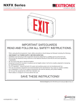
INSTALLATION INSTRUCTIONS
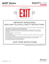
JUNCTION BOX / WALL CEILING MOUNT
1. Remove backplate by pushing through the two tabs at the bottom using a narrow screwdriver.
2. Feed fixture leads through backplate.
3. All Electical connections should be made inside junction box.
Make Electrical Connections as follows:
Note: Cap unused leads to prevent shorting.
4. Mount backplate to junction box using hardware provided with junction box.
5. Connect battery only after continuous AC power can be provided to the unit.
6. Align tabs and push housing directly onto backplate.
120V AC
White - Common
Black - 120V
Green - Ground
277V AC
White - Common
Orange - 277V
Green - Ground Use Flexible Conduit Only.

LED-60 SERIES
INSTALLATION INSTRUCTIONS
800.533.3948 • www.barronltg.com
10070144 Rev 1 - 03/14 2
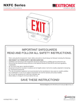
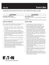
CONDUIT MOUNT
1. Remove backplate by pushing through the two tabs at the bottom using a
narrow screwdriver.
2. Mount backplate to wall surface using keyhole knockouts.
3. Use conduit entry knockouts on backplate and the unit’s housing to
secure conduit.
4. Route fixture leads through hole in conduit flange.
5. All Electrical connections should be made inside junction box.
Make Electrical Connection as follows:
Note: Cap unused leads to prevent shorting.
6. Connect battery only after continuous AC power can be provided to the
unit.
7. Align tabs and push housing directly onto backplate.
OPERATION
1. During and electrical power failure, the LED lamps will automatically
come on for a minimum of 90 minutes.
2. To test, depress the “TEST” switch. The emergency LED lamps will
illuminate. When the switch is releasedthe lamps will go off.
TESTING
The battery supplied with this unit requires no maintenance. However, it should be tested periodically and replaced when
it no longer operates the lamp heads for the duration of 30 seconds. The battery in this unit has a life expectancy of 4
years when used in a normal ambient temperature of 72°F.
Conduit Entry Keyhole Knockouts
Unit
Connector
Locking Tabs
Conduit Entry Knockout
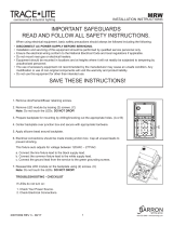
CHARGER
BOARD
277V RED
120V BLACK
0V WHITE
YELLOW (+)
BLUE (-)
YELLOW (+)
BLUE (-)
LAMP
LAMP
TEST
READY
RED
BLACK
BATTERY
WIRING DIAGRAM
NOTE: Unused input
lead must be properly
insulated with wire nut
or other approved
method.
120V AC
White - Common
Black - 120V
Green - Ground
277V AC
White - Common
Orange - 277V
Green - Ground
/