Page is loading ...

Do not use outdoors.
Equipment should be mounted in locations and at heights where it will not be subject to tampering by unauthorized personnel.
Do not mount near gas or electric heaters.
The use of accessory equipment not recommended by the manufacturer may cause an unsafe condition.
Do not use this equipment for anything other than its intended use.
Servicing of this equipment should be performed by qualied personnel.
Disconnect AC power before servicing.
IMPORTANT
The battery in this unit may not be fully charged. After electricity is connected to the
unit for at least 24 hours, then normal operation of this unit should take effect. To
check, press the “TEST” button. The LED lamps on the unit should turn on.
In accordance with NFPA 101, your emergency lighting system must be tested monthly for
a minimum of 30 seconds and annually for 90 minutes. Refer to your local codes for any
additional requirements that may apply.
When re-lamping, use only LED lamps specified in the fixture, using other lamp types may
result in damage or unsafe conditions.
Note: Product complies with California Title 20. Product label is marked with
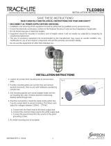
WALL/CEILING MOUNT INSTALLATION
1. Before starting installation, make sure that AC power is turned OFF.
2. Remove unit’s backplate by pushing through the two tabs at the bottom using a narrow screwdriver.
3. Secure backplate to wall surface using keyhole knockouts on the back.
4. Ensure fixture leads are fed through back plate and connect to AC power leads. For 120V, connect the BLACK lead to HOT of the
power supply and for 230V or 277V connect the RED lead. Connect the WHITE lead to NEUTRAL of the supply. Use a wirenut to cap
off the unused lead.
5. When applicable, make wiring connections to the appropriate lamp heads using the YELLOW (+) and BLUE (-) remote leads on the
charger board. Use wirenut(s) to cap off any unused remote lamp head lead(s).
6. Connect battery only after continuous AC power can be provided to the unit.
7. Align tabs and push housing directly onto the backplate. Apply continuous AC power.
J-BOX INSTALLATION (j-box not provided):
1. Before starting installation, make sure that AC power is turned OFF.
2. Remove unit’s backplate by pushing through the two tabs at the bottom using a
narrow screwdriver.
3. Ensure fixture leads are fed through back plate and connect to AC power
leads coming into the junction box.
4. For 120V, connect the BLACK lead to HOT of the power supply and for 230V or
277V connect the RED lead. Connect the WHITE lead to NEUTRAL of the supply.
Use a wirenut to cap off the unused lead.
5. When applicable, make wiring connections to the appropriate lamp heads using
the YELLOW (+) and BLUE (-) remote leads on the charger board. Use wirenut(s)
to cap off any unused remote lamp head lead(s).
6. Mount back plate on J-Box and secure with screws.
7. Connect battery only after continuous AC power can be provided to the unit.
8. Align tabs and push housing directly onto the backplate. Apply continuous AC
power.
NOTE: Max mounting height is 8 ft to achieve at least 1 ft-candle of illuminance in
emergency mode
INSTRUCTIONS
READ AND FOLLOW ALL SAFETY INSTRUCTIONS
SAVE THESE INSTRUCTIONS
and deliver to owner after installation
PAGE: 1 of 2
IMPORTANT SAFEGUARDS
When using electrical equipment, basic safety precautions should always be followed including the following:
READ AND FOLLOW ALL SAFETY INSTRUCTIONS

OPERATION
STANDARD
REMOTE CAPABLE
1. During an electrical power failure, the LED lamps will automatically come on for a minimum of 90 minutes.
2. To test, press the "TEST" switch. The emergency LED lamps will illuminate. When the switch is released, the lamps will go off.
WARNING
Caution: Always turn off AC power to the equipment before servicing. Servicing should be performed only by a qualied service technician.
Use only MANUFACTURER supplied replacement parts.
Battery: The battery supplied with this unit
requires no maintenance. However, it should be tested periodically and replaced when it no
longer operates the lamp heads for the duration of 90 minutes.
The battery in this unit has a life expectancy of up to 4 years when used in a normal ambient temperature
of 72°F.
READ AND FOLLOW ALL SAFETY INSTRUCTIONS
IMPORTANT SAFEGUARDS: When using electrical equipment, always adhere to basic safety precautions including the following :
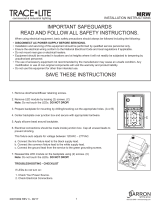
WIRING DIAGRAMS
Note:
Unused input lead must
be properly insulated with
wire nut or other approved
method.
230V or 277V
2
Part No. 912-00053-001
2018.03.01
SAVE THESE INSTRUCTIONS
and deliver to owner after installation
PAGE: 2 of 2
One Lithonia Way, Conyers GA 30012
Phone: 800-334-8694
www.lithonia.com
LED STATUS INDICATOR KEY and TROUBLESHOOTING
Visual Status Indicaon Troubleshoong/Acons to Take
RED
GREEN
UNLIT
1. Baery connecon is not made.
2. Baery has been diagnosed as dead or defecve aer 24
hours of connuous charging with AC power supplied.
Baery is connected, AC power has been supplied and xture is in
charging state.
AC power has not been supplied.
1. Make connecon; or if baery is connected, disconnect
battery for eight seconds and then reconnect.
2. Replace the battery.
This is the normal state. No acon required.
Supply AC power.
120V
Neutral
BLACK (-)
RED (+)
230V or 277V
120V
Neutral
BLACK (-)
RED (+)
/