Page is loading ...

CS005
CS02
CSH02
CSH02FL
CS05
CSE05
CSE05/M8
CSH05
CSH05FL
CS08
CS1
CSE1
CSE1,25/M12
CSH1
CSH1FL
CS1HP
CSH1.2
CSH1.2FL
CSH2FL
CSH3FL
CS2
CSH2
CSE2
CSE2/M16
CS3
CSE3/M24
CS5
CS10
CSG0.50
CSG1.00
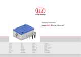
Operating Instructions
capaNCDT 6222

Non-contact Capacitive Displacement Measuring
MICRO-EPSILON
MESSTECHNIK
GmbH & Co. KG
Koenigbacher Str. 15
94496 Ortenburg / Germany
Tel. +49 (0) 8542 / 168-0
Fax +49 (0) 8542 / 168-90
e-mail [email protected]
www.micro-epsilon.com

capaNCDT 6222
Contents
1. Safety ........................................................................................................................................ 7
1.1 Symbols Used ................................................................................................................................................. 7
1.2 Warnings .......................................................................................................................................................... 7
1.3 Notes on CE Marking ...................................................................................................................................... 8
1.4 Intended Use ................................................................................................................................................... 9
1.5 Proper Environment ......................................................................................................................................... 9
2. Functional Principle, Technical Data .................................................................................... 10
2.1 Measuring Principle ....................................................................................................................................... 10
2.2 Structure ........................................................................................................................................................ 11
2.2.1 Sensors ......................................................................................................................................... 12
2.2.2 Sensor Cable ................................................................................................................................ 14
2.2.3 Controller ...................................................................................................................................... 15
2.3 Technical Data ............................................................................................................................................... 17
2.4 Options .......................................................................................................................................................... 18
3. Delivery .................................................................................................................................. 19
3.1 Unpacking, Included in Delivery.................................................................................................................... 19
3.2 Storage .......................................................................................................................................................... 19
4. Installation and Assembly ...................................................................................................... 20
4.1 Precautionary Measures ................................................................................................................................ 20
4.2 Sensor ............................................................................................................................................................ 20
4.2.1 Radial Point Clamping with Grub Screw, Cylindric Sensors ....................................................... 20
4.2.2 Circumferential Clamping, Cylindric Sensors .............................................................................. 21
4.2.3 Flat Sensors .................................................................................................................................. 21
4.2.4 Dimensional Drawings Sensors ................................................................................................... 22
4.3 Sensor Cable ................................................................................................................................................. 30
4.4 Controller ....................................................................................................................................................... 33
4.4.1 Basic Unit, Demodulator Module ................................................................................................. 33
4.4.2 Housing Cover .............................................................................................................................. 34
4.5 Insert Demodulator Module ........................................................................................................................... 35
4.6 Ground Connection, Earthing ....................................................................................................................... 38

capaNCDT 6222
4.7 Electrical Connections ................................................................................................................................... 39
4.7.1 Connectivity Options ................................................................................................................... 39
4.7.2 Pin Assignment Supply, Trigger ................................................................................................... 40
4.7.3 Pin Assignment Analog Output .................................................................................................... 40
5. Operation ................................................................................................................................ 41
5.1 Starting Up ..................................................................................................................................................... 41
5.2 Operating or Display Elements ..................................................................................................................... 41
5.2.1 LED‘s ............................................................................................................................................ 41
5.2.2 Poti ................................................................................................................................................ 42
5.3 Changing Limit Frequency ............................................................................................................................ 43
5.4 Triggering ....................................................................................................................................................... 43
5.5 Measurement Averaging ............................................................................................................................... 45
5.5.1 Introduction .................................................................................................................................. 45
5.5.2 Moving Average ............................................................................................................................ 45
5.5.3 Arithmetic Average Value ............................................................................................................. 46
5.5.4 Median .......................................................................................................................................... 46
5.5.5 Dynamic Noise Rejection ............................................................................................................. 47
6. Ethernet Interface ................................................................................................................... 48
6.1 Hardware, Interface ....................................................................................................................................... 48
6.2 Data Format of Measuring Values ................................................................................................................. 52
6.3 Settings .......................................................................................................................................................... 53
6.4 Commands .................................................................................................................................................... 56
6.4.1 Data Rate (STI) ............................................................................................................................. 56
6.4.2 Trigger Mode (TRG) ...................................................................................................................... 58
6.4.3 Get Measured Data (GMD)........................................................................................................... 58
6.4.4 Filter, Averaging Type (AVT) ......................................................................................................... 59
6.4.5 Filter, Averaging Number (AVN) ................................................................................................... 59
6.4.6 Channel Status (CHS) .................................................................................................................. 60
6.4.7 Mode of Linearization (LIN) .......................................................................................................... 60
6.4.8 Set Linearization Point (SLP) ........................................................................................................ 61
6.4.9 Get Linearization Point (GLP) ....................................................................................................... 62
6.4.10 Status (STS).................................................................................................................................. 62
6.4.11 Version (VER) ............................................................................................................................... 63
6.4.12 Set Mathematic Function (SMF) ................................................................................................... 63
6.4.13 Get Mathematic Function (GMF) .................................................................................................. 65
6.4.14 Clear Mathematic Function (CMF) ............................................................................................... 65
6.4.15 Ethernet Settings (IPS) ................................................................................................................. 66

capaNCDT 6222
6.4.16 Query Data Port (GDP) ................................................................................................................. 66
6.4.17 Set Data Port (SDP) ...................................................................................................................... 66
6.4.18 Access Channel Information (CHI)............................................................................................... 67
6.4.19 Access Controller Information (COI) ............................................................................................ 67
6.4.20 Login for Web Interface (LGI) ....................................................................................................... 68
6.4.21 Logout for Web Interface (LGO) ................................................................................................... 68
6.4.22 Change Password (PWD)............................................................................................................. 68
6.4.23 Change Language for the Web Interface (LNG) .......................................................................... 69
6.4.24 Write Measuring Range Information in Channel (MRA) ............................................................... 69
6.4.25 Set Analog Filter (ALP) ................................................................................................................. 69
6.4.26 Default Messages ........................................................................................................................ 70
6.5 Operation Using Ethernet .............................................................................................................................. 70
6.5.1 Requirements ............................................................................................................................... 70
6.5.2 Access via Web Interface ............................................................................................................. 72
6.5.3 Operating Menu, Set Controller Parameter ................................................................................. 72
6.6 Channel n ....................................................................................................................................................... 73
6.6.1 Channel Information, Measuring Range ...................................................................................... 73
6.6.2 Linearization ................................................................................................................................. 73
6.6.3 Math Function ............................................................................................................................... 75
6.7 Measurement settings ................................................................................................................................... 76
6.7.1 Measurement mode ..................................................................................................................... 76
6.7.1.1 Data Rate ..................................................................................................................... 76
6.7.1.2 Filter type / Averaging ................................................................................................. 77
6.7.1.3 Analog Low Pass Filter ................................................................................................ 77
6.7.2 Trigger Mode ................................................................................................................................ 77
6.8 System Settings ............................................................................................................................................. 78
6.8.1 Language Selection...................................................................................................................... 78
6.8.2 Login, Change of the User Level .................................................................................................. 78
6.8.3 Password ...................................................................................................................................... 79
6.8.4 Ethernet Settings .......................................................................................................................... 79
6.8.5 Import, Export ............................................................................................................................... 80
6.9 Firmware Update ........................................................................................................................................... 81

capaNCDT 6222
7. Measurement .......................................................................................................................... 81
8. Operation and Maintenance .................................................................................................. 82
9. Liability for Material Defects .................................................................................................. 83
10. Decommissioning, Disposal .................................................................................................. 83
Appendix ................................................................................................................................................ 84
A 1 Accessories, Service .............................................................................................................. 84
A 1.1 Conversion Kit ................................................................................................................................................ 84
A 1.3 PC6200-3/4 .................................................................................................................................................... 86
A 1.4 Optional Accessories ..................................................................................................................................... 86
A 1.5 Service ........................................................................................................................................................... 89
A 2 Factory Setting ....................................................................................................................... 90
A 3 Tilt Angle Influence on the Capacitive Sensor ..................................................................... 91
A 4 Measurement on Narrow Targets .......................................................................................... 92
A 5 Measurements on Balls and Shafts ...................................................................................... 93

Page 7
Safety
capaNCDT 6222
1. Safety
System operation assumes knowledge of the operating instructions.
1.1 Symbols Used
The following symbols are used in these operating instructions:
Indicates a hazardous situation which, if not avoided, may result in minor or moder-
ate injury.
Indicates a situation that may result in property damage if not avoided.
Indicates a user action.
i
Indicates a tip for users.
Measure
Indicates hardware or a software button/menu.
1.2 Warnings
Disconnect the power supply before touching the sensor surface.
> Danger of injury
> Static discharge
Connect the power supply and the display/output device according to the safety regulations for electrical
equipment.
> Risk of injury
> Damage to or destruction of the sensor and/or controller
Avoid shocks and impacts to the sensor and controller.
> Damage to or destruction of the sensor and/or controller
The supply voltage must not exceed the specified limits.
> Damage to or destruction of the sensor and/or controller

Page 8
Safety
capaNCDT 6222
Protect the sensor cable against damage.
> Destruction of the sensor
> Failure of the measuring device
1.3 Notes on CE Marking
The following apply to the capaNCDT 6222:
- EU directive 2004/108/EU
- EU directive 2011/65/EU, “RoHS“ Category 9
Products which carry the CE mark satisfy the requirements of the EU directives cited and the European
harmonized standards (EN) listed therein. The EU Declaration of Conformity is available to the responsible
authorities according to EU Directive, article 10, at:
MICRO-EPSILON Messtechnik GmbH & Co. KG
Koenigbacher Str. 15
94496 Ortenburg / Germany
The measuring system is designed for use in industrial environments and meets the requirements.

Page 9
Safety
capaNCDT 6222
1.4 Intended Use
- The capaNCDT 6222 measuring system is designed for use in industrial areas. It is used for
displacement, distance, thickness and movement measurement
position measuring of parts or machine components
- The system must only be operated within the limits specified in the technical data, see Chap. 2.3.
- The system must be used in such a way that no persons are endangered or machines and other material
goods are damaged in the event of malfunction or total failure of the system
- Take additional precautions for safety and damage prevention in case of safety-related applications.
1.5 Proper Environment
- Protection class: IP 40
- Temperature range:
Operation
• Sensor: -50 ... +200 °C (-58 to +392 °F)
1
• Sensor cable: -100 ... +200 °C (-148 to +392 °F) (CCmx and CCmx/90)
-20 ... +80 °C (-4 to +176 °F) (CCgx and CCgx/90 - permanently)
-20 ... +100 °C (-4 to +212 °F) (CCgx and CCgx/90 - 10,000 h)
• Controller: +10 ... +60 °C (+50 to +140 °F)
Storage
• Sensor: -50 ... +200 °C (-58 to +392 °F)
2
• Sensor cable: -50 ... +200 °C (-58 to +392 °F) (CCmx and CCmx/90)
-50 ... +80 °C (-58 to +176 °F) (CCgx and CCgx/90)
• Controller: -10 ... +75 °C (+14 to +167 °F)
- Humidity: 5 - 95 % (non-condensing)
- Ambient pressure: Atmospheric pressure
- The space between the sensor surface and the target must have an unvarying dielectric constant.
- The space between the sensor surface and the target may not be contaminated (for example water,
rubbed-off parts, dust, etc)
1) An operating temperature of -50 ... +100 °C (-58 to +212 °F) applies for the sensors CSG0.50-CA and
CSG1.00-CA -50
2) A storage temperature of -50 ... +100 °C (-58 to +212 °F) applies for the sensors CSG0.50-CA and
CSG1.00-CA -50

Page 10
Functional Principle, Technical Data
capaNCDT 6222
2. Functional Principle, Technical Data
2.1 Measuring Principle
The principle of capacitive distance measurement with the capaNCDT system is based on the principle of the
parallel plate capacitor. For conductive targets, the sensor and the target opposite form the two plate elec-
trodes.
If a constant AC current flows through the sensor capacitor, the amplitude of the AC voltage at the sensor is
proportional to the distance between the capacitor electrodes. The AC voltage is demodulated, amplified and
output as an analog signal.
The capaNCDT system evaluates the reactance X
C
of the plate capacitor which changes strictly in proportion
to the distance.
X = ; capacitance C = * *
c
1
jC
area
distance
r
o
i
A small target and bent (uneven) surfaces cause a non-linear characteristic.
This theoretical relationship is realized almost ideally in
practice by designing the sensors as guard ring capaci-
tors.
The linear characteristic of the measuring signal is
achieved for electrically conductive target materials
(metals) without any additional electronic linearization.
Slight changes in the conductivity or magnetic proper-
ties do not affect the sensitivity or linearity.
Electrical conductor
Ground
Screening electrode
Measuring electrode
Fig. 1 Functional principle of the guard ring
capacitor

Page 11
Functional Principle, Technical Data
capaNCDT 6222
2.2 Structure
The non-contact, multi-channel measuring system, installed in an aluminum housing, consists of:
- A basic module DT6222
- A demodulator module DL6222x with integrated preamplifier per sensor
- Sensor
- Sensor cable
- Power supply cable
- Ethernet cable
- Signal output cable
The modular assembly allows to join up to 4 channels (module system).
Micro controller
Demodulator
Preamplifier
A/D
converter
Voltage
0..10 V
Current
4..20mA
Sensor
Output circuit
Analog filter
digital
switchable
Zero point
adjustable
poti
Demodulator
Preamplifier
A/D
converter
Voltage
0..10 V
Current
4..20mA
Sensor
Output circuit
Analog filter
digital
switchable
Zero point
adjustable
poti
DT6222 DL6222 DL6222
Oscillator
Voltage
conditioning
Trigger
Supply
12 ... 36 V
Ethernet
Fig. 2 Block diagram capaNCDT 6222

Page 12
Functional Principle, Technical Data
capaNCDT 6222
2.2.1 Sensors
For this measurement system, several sensors can be used.
In order to obtain accurate measuring results, keep the surface of the sensor clean and free from dam-
age.
The capacitive measuring process is area-related. A minimum area (see table) is required depending on the
sensor model and measuring range. In the case of insulators the dielectric constant and the target thickness
also play an important role.
Sensors for electrical conducting targets (metals)
Sensor model Measuring range Min. target diameter
CS005 0.05 mm 3 mm
CS02 0.2 mm 5 mm
CSH02 0.2 mm 7 mm
CSH02FL 0.2 mm 7 mm
CS05 0.5 mm 7 mm
CSE05 0.5 mm 6 mm
CSE05/M8 0,5 mm 6 mm
CSH05 0.5 mm 7 mm
CSH05FL 0.5 mm 7 mm
CS08 0.8 mm 9 mm
CS1 1 mm 9 mm
CSE1 1 mm 8 mm
CSE1,25/M12 1,25 mm 10 mm
CSH1 1 mm 11 mm
CSH1FL 1 mm 11 mm
CS1HP 1 mm 9 mm

Page 13
Functional Principle, Technical Data
capaNCDT 6222
Sensor model Measuring range Min. target diameter
CSH1,2 1.2 mm 11 mm
CSH1.FL 1.2 mm 11 mm
CSH2FL 2 mm 17 mm
CS2 2 mm 17 mm
CSH2 2 mm 17 mm
CSE2 2 mm 14 mm
CSE2/M16 2 mm 14 mm
CS3 3 mm 27 mm
CSE3/M24 3 mm 20 mm
CSH3FL 3 mm 24 mm
CS5 5 mm 37 mm
CS10 10 mm 57 mm
CSG0.50 0.5 mm appr. 7 x 8 mm
CSG1.00 1.00 mm appr. 8 x 9 mm

Page 14
Functional Principle, Technical Data
capaNCDT 6222
2.2.2 Sensor Cable
Sensor and controller are connected by a special, double screened sensor cable.
Do not shorten or lengthen these special cables.
Usually, a damaged cable can not be repaired.
Switch off the device when plugging and removing connectors.
Do not crush the sensor cable.
Do not modify to the sensor cable.
> Lost of functionality
Model Cable length Cable ø 2 axial
connector
1x axial
+ 1x 90
0
For sensors Min. bending radius
once permanently
CCgxC 2/4 m 3.1 mm • 0.05 - 0.8 mm
10 mm 22 mm
CCgxC/90 2/4 m 3.1 mm • 0.05 - 0.8 mm
CCgxB 2/4 m 3.1 mm • 1 ... 10 mm
CCgxB/90 2/4 m 3.1 mm • 1 ... 10 mm
CCmxC 1.4/2.8 m 2.1 mm • 0.05 - 0.8 mm
7 mm 15 mm
CCmxC/90 1.4/2.8 m 2.1 mm • 0.05 - 0.8 mm
CCmxB 1.4/2.8 m 2.1 mm • 1 ... 10 mm
CCmxB/90 1.4/2.8 m 2.1 mm • 1 ... 10 mm
The sensors of type CSH have integrated a 1.4 long sensor cable. Cable lengths of 2.8 m are available too if
required.
Other cable lengths are also available on request.
The sensor model CSE1 (measuring range 1 mm) has the connector type C.

Page 15
Functional Principle, Technical Data
capaNCDT 6222
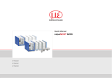
2.2.3 Controller
The capaNCDT 6222 Multi-channel measuring system consists of a basic module DT62xx and one up to four
demodulator modules DL62xx, according to requirements. The components are stored in aluminum hous-
ings.
Basic module
Demodulator module(s)
Fig. 3 Front view basic module DT6222 with 4 demodulator modules DL6222

Page 16
Functional Principle, Technical Data
capaNCDT 6222
Basic module DT6222
The basic module DL62xx consists of the units voltage conditioning, oscillator and digital unit.
The voltage conditioning generates all required internal voltages from the supply voltage, both for the basic
module as well as the connected demodulator modules. The oscillator supplies the demodulator modules
with constant frequency and amplitude-stable alternating current. The frequency is 62 kHz. The digital unit
controls the A/D converter of the demodulator modules and measures the actual measuring values. The mea-
suring values can be read out via the Ethernet interface in digital form, see Chap. 6.
Demodulator module DL6222
The demodulator module DL62xx consists of an internal preamplifier, demodulator, output stage and A/D
converter. The internal preamplifier generates the distance dependent measuring signal and amplifies it. De-
modulator and output stage convert the measuring signal in a standardized voltage and current signal. The
measuring values can be processed digitally with the help of the A/D converter.
The trim potentiometer zero allows a special zero adjustment of the analog output signals, see Fig. 3.
i
Output voltage can achieve up to 15 VDC, if the sensor is disconnected respectively exceedance of
measuring range.

Page 17
Functional Principle, Technical Data
capaNCDT 6222
2.3 Technical Data
Controller type DL6222 DL6222/ECL2
Resolution dynamic 0.05 % FSO (20 kHz) 0.1 % FSO (20 kHz)
Bandwidth 20 kHz (-3dB) 20 kHz (-3dB)
Bandwidth adjustable to 20 Hz to 20 Hz
Data rate output digital max. 3.906 kSa/s max. 3.906 kSa/s
Linearity (typical) ≤ ±0,1 % d.M. ≤ ±0,2 % d.M.
Max. sensitivity deviation ≤ ±0.1 % FSO ≤ ±0.1 % FSO
Long term stability ≤ 0.02 % FSO / month ≤ 0.02 % FSO / month
Synchronous operation supported
(multiple control units)
no no
Isolator measurement no no
Temperature stability 200 ppm 200 ppm
Temperature range
Operation
Sensor
1
-50 ... +200 °C (-4 ... +392 °F) -50 ... +200 °C (-4 ... +392 °F)
Controller +10 … +60 °C (+50 ... +140 °F) +10 … +60 °C (+50 ... +140 °F)
Storage -10 … +75 °C (+14 ... +167 °F) -10 … +75 °C (+14 ... +167 °F)
Supply 24 VDC (12 … 36 VDC) 24 VDC (15 … 36 VDC)
Power consumption at
24 VDC
DT6222 2.8 W (typical)
per DL6222 1.2 W (typical); 1.4 W (max.)
Output
0 … 10 V (short-circuit proof) 0 … 10 V (short-circuit proof)
4 … 20 mA (load max. 500 Ohm) 4 … 20 mA (load max. 500 Ohm)
Ethernet Ethernet
Sensors all sensors suitable all sensors suitable
Sensor cable standard CCm1.4x; CCg2.0x CCm2.8x; CCg4.0x
Sensor cable (matched) ≤ 2.8 m (mit CCmxx) ≤ 4.0 m (mit CCgxx) ≤ 2.8 m (mit CCmxx) ≤ 4.0 m (mit CCgxx)
Trigger TTL, 5 V TTL, 5 V
FSO = Full Scale Output
1) A storage temperature of -50 ... +100 °C (-58 to +212 °F) applies for the sensors CSG0.50-CA and CSG1.00-CA -50

Page 18
Functional Principle, Technical Data
capaNCDT 6222
2.4 Options
Article number Designation Description
Suitable for articles
2303035
DL6222
2303036
DL6222/ECL2
2303038
DL6222/LC
2982045
LC DL62x0
analog
Special calibration of linearity on digital
output
○ ○
•
2982059 ECL2 DL6222
Special set-up for 2-way sensor cable
length
- • •
2982061 EMR2 DL6222
Extended measuring range
(factor: 2)
○ ○
•
2982062 RMR1/2 DL6222
Shortened measuring range
(factor: 1/2)
○ ○
•
• Articles already contain the option
○ Option available
- No option available

Page 19
Delivery
capaNCDT 6222
3. Delivery
3.1 Unpacking, Included in Delivery
1 Basic module DT62x0 with 1 - 4 demodulator modules DL62x0
1 Power supply and trigger cable PC6200-3/4, 3 m long, see Chap. A 1.3
1 Ethernet cable, 3 m long
1 CD (contains instruction manual and software)
1 Conversion kit (Springs for mounting on DIN-rail, mounting plates for wall fastening, threaded rods in differ-
ent lengths), see Chap. A 1.1.
Optional accessories:
1 Sensor
1 Sensor cable with connector
1 Signal output cable, see Chap. A 1.4
Carefully remove the components of the measuring system from the packaging and ensure that the
goods are forwarded in such a way that no damage can occur.
Check the delivery for completness and shipping damage immediately after unpacking.
If there is damage or parts are missing, immediately contact the manufacturer or supplier.
3.2 Storage
- Temperature range storage:
Sensor: -50 ... +200 °C (-58 to +392 °F)
1
Sensor cable: -50 ... +200 °C (-58 to +392 °F) (CCmx and CCmx/90)
-50 ... +80 °C (-58 to +176 °F) (CCgx and CCgx/90)
Controller: -10 ... +75 °C (+14 to +167 °F)
- Humidity: 5 - 95 % RH (non-condensing)
1) A storage temperature of -50 ... +100 °C (-58 to +212 °F) applies for the sensors CSG0.50-CA and
CSG1.00-CA -50

Page 20
Installation and Assembly
capaNCDT 6222
4. Installation and Assembly
4.1 Precautionary Measures
No sharp-edged or heavy objects may get into contact with the sensor cable sheath.
Protect the cable against pressure loads in pressurised rooms.
Avoid kinks in any case.
Check the connections for tight fit.
i
A damaged cable cannot be repaired.
4.2 Sensor
The sensors may be mounted free-standing or ush.
When assembling, make sure that the polished sensor surface is not scratched.
4.2.1 Radial Point Clamping with Grub Screw, Cylindric Sensors
This simple type of fixture is only recommended for a force and vibration-free installation position. The grub
screw must be made of plastic so that it cannot damage or deform the sensor housing.
Grub screw
Fig. 4 Radial point clamping with grub screw
Do not use metal grub screws!
> Danger of damaging the sensor
/