Page is loading ...

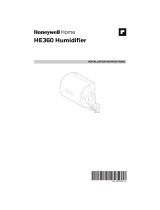
Typical Installation Locations
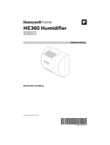
Installation
1. Turn off power to the air handling
system at the circuit breaker.
2. Draw a level line on the plenum in the
selected location.
IMPORTANT
Be sure the mounting template is level
before marking. Use of a small level is
recommended.
3. Tape the correct template in position
and trace around the template.
4. Remove the template and carefully
cut the opening with tin snips.
5. Disassemble the humidifier; remove
the cover and take out the humidifier
pad assembly.
6. Make sure the humidifier housing is
level, then position it in the opening
so the plastic tabs are in place on
the lower sheet metal edge of the
opening. Use pliers, as necessary, to
flatten cut edges.
7. Secure the humidifier housing to the
opening at the top and bottom using
sheet metal screws.
8. Reassemble humidifier side plates
to customize the orientation for your
specific install. The side plate with
the humidifier port needs to be on
the side of the humidifier that is
closest to the bypass ducting. Be sure
to open the bypass flap for use and
close it when the humidifier is not
used.
HE105, HE205 Humidifier
This Quick Start Guide is sized to serve as a duct template for the HE205.
Cut along the dashed line to create a duct template for the HE105.
QUICK START GUIDE
Included in the box:
• Humidifier
• H6062 Humidistat
• Transformer
Canadian "C" models also include:
• 6 in. dia. bypass ducting (24 in.)
• 18 gauge thermostat wire (20 ft.)
• 1/4 in. (6.35 mm) OD feed water tubing
(20 ft.)
• 1/2 in. (12.7 mm) ID drain tubing (10 ft.)
• Saddle valve
Tools Required:
• Tin snip
• Screwdriver
• Pliers
• Adjustable or open-end wrench
• Drill
• Level
• 3/4 in. (19 mm) sheet metal drill bit
WARNING
CAUTION
DANGER
NOTICE
PMS 144
PMS 108
PMS 185
PMS 299
Personal Injury Hazard
Can cause electrical shock and injury
from moving parts.
Disconnect power and shut off water
supply before removing cover.
Hazardous Voltage
Can cause personal injury or equipment
damage.
Do not cut or drill into any air
conditioning or electrical accessory.
WARNING
CAUTION
DANGER
NOTICE
PMS 144
PMS 108
PMS 185
PMS 299
Chemical Hazard
Can cause personal injury or equipment
damage.
Do not use any line connected to an air
conditioner.
Do not use gas line.
Temperature and Static Pressure
Hazard
Can cause property or equipment
damage.
Locate humidifier where ambient
temperature is between 41 and 113 °F
(5 to 45 °C).
Do not install humidifier where freezing
temperatures could occur.
Be sure supply plenum static pressure
is no greater than 0.4 in. wc and water
pressure is no greater than 120 psi.
Sharp Edges Installation Hazard
Can cause personal injury.
Wear gloves and safety glasses.
M12248D
HORIZONTAL
DOWN
FLO
LOWBOY
HIGHBOY
HUMIDIFIER
BYP
ASS
COLLAR
M31022A
WATER
FEED NOZZLE
FRAME
HUMIDIFIER
HOUSING
WATER
FEED TUBE
HUMIDIFIER
PAD ASSEMBLY
COVER
SIDEWALL
BY-PASS SIDEWALL
9. Slide bypass duct over the humidifier
port on the HE105/HE205, making
sure that the flex duct advances past
the raised plastic tabs on the port.
These tabs will help to hold the flex
duct in place. Verify that the damper
blade has adequate clearance to
move back and forth between the
closed and open positions. Secure
the flex duct in place with the plastic
connector strap.
10. Seal the duct connections with foil
tape. Seal both 1) the connection
between the starter collar end of
the flex duct and the home's duct
work and 2) the end of the flex duct
to the humidifier over the top of the
connector strap.
11. Reinstall the humidifier pad
assembly in the humidifier housing.
12. Hinge the cover in place and secure
with the thumbscrew located at the
bottom of the cover.
13. Turn off water supply and tap into a
water line.
14. Use 1/4 in. O.D. copper tubing and
connect to inlet side of solenoid
valve via a compression fitting or
Resideo Quick Connect fitting.
15. Connect a 1/2 in. (13 mm) drain
tube to the humidifier drain fitting
and run to a suitable drain.
Cut along dashed line to create a template for the HE105.
Use the full sheet for the HE205
Resideo Inc., 1985 Douglas Drive North
Golden Valley, MN 55422
33-00210—05 M.S. Rev. 06-22 | Printed in United States
www.resideo.com
© 2022 Resideo Technologies, Inc. All rights reserved.
The Honeywell Home trademark is used under license from Honeywell International, Inc.
This product is manufactured by Resideo Technologies, Inc. and its affiliates.
33-00210-05

Wiring
Specifications
HE105 HE205
Size
length × width × depth
15.16 × 16.57 × 9.47 in.
(385 × 421 × 240 mm)
18.30 × 17.11 × 9.59 in.
(465 × 434 × 243 mm)
Duct Opening
height × width
9.43 × 9.28 in.
(240 × 236 mm)
12.63 × 9.68 in.
(321 × 246 mm)
Replacement Pad HC22 HC26
Pad Size 10 × 9.5 × 1.5 in.
(254 × 241 × 38.1 mm)
13.125 × 10 × 1.5 in.
(333 × 254 × 38.1 mm)
Evaporation Output 12 GPD 17 GPD
Orice Output .02 in. (0.5 mm)
Flow Rate at Nozzle 4.7 GPH (18 L/hr.) under 120 psi
Operating Ambient
Temperature
41 to 113°F
5 to 45°C
Power Supply 24 VAC / 60 Hz.
Power Consumption 7 Watts with 24 Vrms
Water Pressure 40 to 120 psi.
CHECKOUT
Humidifier is level.
Control wiring was reviewed using circuit
diagram.
Feed line has no kinks.
Drain line slopes continuously down and
ends at floor drain.
Water hose inside humidifier is connected
to PerfectFLO™ water distribution tray.
Follow these steps to check operation:
1. Turn on power and water supply
2. Ensure water supply is fully opened.
3. Turn the humidistat to up to call for
humidity and turn on the heat by setting
the thermostat to 10 ºF (6 ºC) above room
temperature.
IMPORTANT
The furnace blower must be on to activate the
humidifier.
4. Make sure that water is flowing out of the
drain hose.
5. Check for leaks.
6. Reset the thermostat and humidistat to a
comfortable setting for automatic operation.
(35% RH is recommended.)
NEED HELP?
For assistance with this product please visit honeywellhome.com
or call Customer Care toll-free at 18004681502.
* When a thermostat with IAQ control is used instead of a humidistat, it simplifies the wiring circuit. The thermostat U contacts are installed
in place of the H6062 from Fig. 3 and the sail switch is removed from the circuit. No special wiring of the transformer primary, sail switch,
or relay is needed.
Fig. 1. Wiring H6062 to humidifier with Fan Interlock.
M34570A
1
TRANSFORMER
FURNACE
FAN
MOTOR
FAN CONTROL
L1
(HO
T)
L2
POWER
SUPPLY
1
2
PROVIDE DISCONNECT MEANS AND
OVERLOAD PROTECTION AS REQUIRED.
24 VAC WIRING.
HUMIDIFIER
2
C
R
U
U
S
S
24V CONSTANT
REQUIRED
OUTDOOR SENSOR
Fig. 4. Wiring HumidiPRO with current-sensing
relay.
M34572A
1
L1
(HOT)
L2
1PROVIDE DISCONNECT MEANS AND OVERLOAD PROTECTION AS REQUIRED.
HUMIDIFIER
C
R
U
U
S
SOUTDOOR SENSOR
CURRENT
SENSING
RELAY
CHI
LO
24V CONSTANT
REQUIRED
Fig. 3. Wiring HumidiPRO with 2-speed fan motor.*
M34571
1
TRANSFORMER
2-SPEED
FAN MOTOR
FAN CONTROL
L1
(HO
T)
L2
POWER
SUPPLY
1
2
PROVIDE DISCONNECT MEANS AND OVERLOAD PROTECTION AS REQUIRED.
24 VAC WIRING.
HUMIDIFIER
2
C
R
U
U
S
S
24 VAC (CONSTANT)
OUTDOOR SENSOR
DPST
SWITCHING
RELAY
HL
C
M34573A
1
L1
(HOT)
L2
1
PROVIDE DISCONNECT MEANS AND OVERLOAD PROTECTION AS REQUIRED.
HUMIDIFIER
C
R
U
U
S
SOUTDOOR SENSOR
AIR PRESSURE
SWITCH/SAIL
SWITCH
24V CONSTANT
REQUIRED
Fig. 2. Wiring HumidiPRO in line with air
proving device.
/