HE220, HE260 HUMIDIFIER INSTALLATION KIT
69-2518—03 2
Required Tools
Tools required for installation include:
• Tin snip.
• Screwdriver.
• Adjustable or open-end wrench.
• Drill, punch or awl.
•Level.
• 3/4-in. Sheet Metal Drill Bit
Determining Best Location for
Humidifier
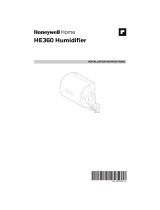
• Select a location for the humidifier on the supply (warm
air stream) or the return plenum. See Fig. 1.
• Select a location for the bypass on the opposite
plenum. The sidewalls of the humidifier are
interchangeable to allow bypass duct mounting on
either side of the humidifier.
• Select a location that cannot damage the air
conditioner A-coil during installation.
• Select a location where the 6 ft (1.86m) of 6 in. (155
mm) duct provided is adequate to connect the
humidifier to the bypass.
— Do not locate the humidifier or bypass on a fur-
nace body.
— Allow adequate clearance in front of and above
the humidifier so you can easily remove the cover
to perform routine maintenance.
— Mount humidifier at least 3 in. (78 mm) above the
furnace body to allow adequate space for the
solenoid valve and drain line.
— Mount humidifier in a conditioned space to prevent
freezing.
Fig. 1. Typical humidifier installation locations.
Selecting Water Supply Location
• Use either hard or soft water in the humidifier and
either hot or cold water. The water flow rate, with the
humidifier running, is 3.5 gal/hr (13 liters/hr) to flush
the pad and provide moisture for evaporation.
• Make sure that the 20 ft (6.2m) of feed water tubing
provided is adequate to connect the water supply
(saddle valve) with the humidifier solenoid valve.
Locating Closest Floor Drain
• Select location with access to a floor drain to provide
drainage for air conditioner condensation and
humidifier drainage.
• If you do not have a drain available, we recommend
that you install the Honeywell Whole House Drum or
Disk Humidifier.
• Make sure that the 10 ft (3.1m) of drain tubing is
adequate to reach from the humidifier drain connection
to the floor drain.
Mount the switch at least 6 in. (152 mm) upstream from
an elbow or junction, and at least 15 in. (381 mm)
downstream from an elbow or junction. Locate the switch
on the opposite side of the duct from the air entrance.
(See Fig. 1-3 in S688 Installation Instructions.)
Selecting Location for Humidistat
• Select a location for the humidistat on the return
plenum or on the wall in the living space.
— Mounting on the return plenum is the easiest
installation for the control wiring circuit.
For return duct mounting, the humidistat should be
mounted upstream from the humidifier or bypass so that it
is properly sensing the relative humidity of the living
space. Locate the control at least 8 in. (203 mm)
upstream from the humidifier in the return air duct. (See
Fig 2.)
Air Pressure Switch and Accessories
2 Black rubber gasket
2 Tubing Fitting Elbow
1 10 ft. Tubing, 1/4 in. ID
1 Air Pressure Switch (Fig. 10)
2 Screws, #8 x 3/4 in. sheet metal
2 Terminal Adaptor
Table 1. Required Accessories.
Quantity Accessory
M27302
M27323
M12248D
HORIZONTAL
DOWN
FLO
LOWBOY
HIGHBOY
HUMIDIFIER
BYPASS
COLLAR