Honeywell HE265A User manual

Category
Fireplaces
Type
User manual
PRODUCT DATA
® U.S. Registered Trademark
Copyright © 2000 Honeywell • All Rights Reserved
HE225A,B and HE265A,B
Bypass Flow-Through
Humidifier
APPLICATION
The Enviacaire Elite HE225A,B and HE265A,B Bypass Flow-
through Humidifiers use the warm air furnace blower to
provide humidification for the whole house.
FEATURES/BENEFITS
Antimicrobial coating on pad prevents the surface
growth and migration of bacteria, mold, fungus and
algae on the humidifier pad.
Bold new look with blue and white styling.
Proven technology used for high performance
humidification and enhanced comfort.
Preassembled for quicker installation.
Small footprint, light weight and reversible
components allow easy mounting on either warm air
supply or return air duct of any forced air furnace.
Interior components designed for quick maintenance
and service.
Includes easy-to-use humidity control that mounts on
the wall or duct for more flexible installation.
Continuous flushing reduces the frequency of
maintenance in a hard water installation.
AIRWATCH™ Indicator can be installed to remind
homeowner to change humidifier pad.
Five-year warranty.
whole-house air quality system
68-0244
HE225A,B AND HE265A,B BYPASS FLOW-THROUGH HUMIDIFIER
68-0244
2
ORDERING INFORMATION
When purchasing replacement and modernization products from your TRADELINE® wholesaler or distributor, refer to the
TRADELINE® Catalog or price sheets for complete ordering number.
If you have additional questions, need further information, or would like to comment on our products or services, please write or
phone:
1. Your local Home and Building Control Sales Office (check white pages of your phone directory).
2. Home and Building Control Customer Relations
Honeywell, 1985 Douglas Drive North, MN10-1461
Golden Valley, Minnesota 55422-4386 1-800-468-1502
In CanadaHoneywell Limited/Honeywell Limitée, 35 Dynamic Drive, Scarbouorgh, Ontario M1V 4Z9.
International Sales and Service Offices in all principal cities of the world. Manufacturing in Australia, Canada, Finland, France,
Germany, Japan, Mexico, Netherlands, Spain, Taiwan, United Kingdom, U.S.A.
SPECIFICATIONS
Capacity:
At 120°F (49°C) plenum temperature and 0.20 static
pressure drop across supply and return:
HE225A,B: 12 gallons per day (gpd) or 46 liters per
day (lpd).
HE265A,B: 17 gallons per day (gpd) or 65 liters per
day (lpd).
Electrical Ratings:
24 Vac, 60 Hz, 0.5A.
Humidified Area:
See Table 1.
Humidifier Pad Dimensions:
See Table 2.
Plenum Opening Dimensions (Height x Width):
See Table 3.
Summer Shut-off Damper Dimensions (Height x Width):
See Table 4.
Bypass Duct Opening (Diameter):
6 in. (152 mm).
Drain Connection:
1/2 in. (13 mm) I.D. plastic hose connected directly to drain
fitting on unit.
Dimensions:
Refer to Fig. 1 and 2.
Table 1. Size Of Area That Can Be Humidified.
Table 2. Dimensions Of Humidifier Pads In In. (mm).
Table 3. Dimensions Of Plenum Opening In In. (mm).
Table 4. Dimensions Of Summer Shut-off Damper
In In. (mm).
HE225 Area (Up To) HE265 Area (Up To)
House Description Air Changes Per Hour Sq ft Sq m Sq ft Sq m
Loose Two 750 70 1,000 93
Average One 1,500 140 2,000 186
Tight One-half 3,000 280 4,000 372
Model Height Width Depth
HE225 9-13/16 (249) 9-1/2 (241) 1-1/2 (38)
HE265 13 (330) 10 (254) 1-1/2 (38)
Model Height Width
HE225 9-7/16 (241) 9-5/16 (238)
HE265 12-5/8 (321) 9-3/4 (248)
Model Height Width
HE225 9-3/16 (234) 8-7/8 (226)
HE265 12-3/8 (314) 9-5/16 (236)
HE225A,B AND HE265A,B BYPASS FLOW-THROUGH HUMIDIFIER
68-0244
3
Fig. 1. Dimensions of HE225A,B in in. (mm).
Fig. 2. Dimensions of HE265A,B in in. (mm).
Approvals:
Underwriters Laboratories Inc. Listing: 56 BL.
Canadian Underwriters Laboratories Inc. Listing: 56 BL.
Standard:
Air Conditioning and Refrigeration Institute Tested:
Standard 610.
Models:
HE225A TRADELINE® and HE265A TRADELINE®
Bypass Flow-through Humidifier package includes
humidifier pad, mounting template, self-piercing saddle
valve, 24 Vac transformer, H8908B Convertible
Humidity Control.
HE225B TRADELINE® and HE265B TRADELINE®
Bypass Flow-through Humidifier package includes
humidifier pad, mounting template, self-piercing saddle
valve, 24 Vac transformer, H1008A Automatic Humidity
Control with HumidiCalc™ Software.
Accessories:
Current Sensor Relay, part no. 32001754-001.
C7089H Outdoor Temperature Sensor.
H8908B Convertible Humidity Control.
H1008A Automatic Humidity Control with HumidiCalc+™
Software (software calculates dewpoint to prevent
moisture condensation).
HC22E Antimicrobial Humidifier Pad (HE225A,B only).
HC26E Antimicrobial Humidifier Pad (HE265 A,B only).
HumidiCalc+™ Humidifier Sizing Software (software
calculates required humidifier capacity for application).
PC8900 Control.
S688 Sail Switch.
INSTALLATION
WARNING
Hazardous Voltage.
Can cause personal injury or equipment damage.
Do not cut or drill into any air conditioning line or
electrical accessory.
CAUTION
Freezing Water, Flooding or
Static Pressure Hazard.
Can cause water damage to home or permanent
equipment damage.
The humidifier must be located where the ambient
temperature is above 32°F and below 160°F (0°C
and 71°C).
Be sure supply plenum static pressure is no
greater than 0.3 in. w.c. and water pressure is no
greater than 125 psi.
IMPORTANT
To assure optimal product performance, be sure the
template is level before marking location.
1. Determine the best location for the humidifier and draw
a level line on the plenum. See Fig. 3.
M14818
9-1/8 (232)
1
1
-7
/1
6 (29
0
)
12-7/16
(316)
6 (152)
DIAMETER
1
2 (3
05)
13-9/16
(345)
M14819
9-1/4 (235)
12 (305)
15-5/16
(390)
13-9/16 (345)
16-3/4
(425)
6 (152)
DIAMETER
HE225A,B AND HE265A,B BYPASS FLOW-THROUGH HUMIDIFIER
68-0244
4
Fig. 3. Typical humidifier installation locations.
IMPORTANT
Mount the humidifier at least 3 in. (76 mm) above
the furnace jacket to allow adequate space for the
solenoid valve and drain line. Check that there is
adequate space above the humidifier to remove and
install the humidifier cover.
2. Tape the template in position and trace around the
template.
3. Remove the template and carefully cut the rectangular
opening.
4. Disassemble the humidifier; remove the cover and take
out the humidifier pad assembly. See Fig. 4.
NOTE: Sidewalls are interchangeable for either left or
right by-pass installation. To change direction,
remove the screws holding each sidewall,
switch sidewall locations and reinstall the
screws.
5. Position the humidifier housing in the opening (be sure
it is level), so the locking tabs are in place on the lower
sheet metal edge of the opening.
6. Secure the humidifier housing to the opening at the top
and bottom using sheet metal screws.
7. Locate the other plenum and cut an opening for a 6 in.
(152 mm) collar.
8. Install the 6 in. (152 mm) collar.
NOTE: Be sure to install a duct damper for summer
shutoff on systems with air conditioning.
9. Install a 6 in. (152 mm) diameter duct from the collar to
the humidifier.
NOTE: Some installations require a 90° elbow
attachment to the collar.
10. Seal the duct connections with duct tape.
NOTE: To avoid sagging and stress on the humidifier,
add support when ducting is longer than
4 ft (120 cm).
11. Reinstall the humidifier pad assembly in the humidifier
housing.
NOTE: Be sure the water feed tube is not pinched or
kinked.
12. Hinge the cover in place and secure with the
thumbscrew located at the bottom of the cover.
Fig. 4. Humidifier components.
WIRING THE HUMIDIFIER
CAUTION
Hazardous Voltage.
Can cause personal injury or equipment damage.
Disconnect the power supply before installing or
servicing.
On multispeed blower applications, do not wire the
high voltage side of the transformer to the same
power source that services the furnace blower.
Premature transformer burnout may occur.
All wiring must comply with applicable local codes,
ordinances and regulations.
1. Mount the transformer in a convenient location.
2. Connect wires to the 120V side of the transformer.
3. Wire the humidifier solenoid valve, current sensing
relay, or sail switch, humidity control and transformer.
Refer to the humidity control installation instructions for
mounting and wiring information.
NOTE: Select models of fan centers include humidifier taps
so the current sensing relay or sail switch is not
needed.
M12248C
HORIZONTAL
DOWN
FLO
LOWBOY
HIGHBOY
M14672
WATER
FEED NOZZLE
FRAME
HUMIDIFIER
HOUSING
WATER
FEED TUBE
HUMIDIFIER
PAD ASSEMBLY
COVER
SIDEWALL
BY-PASS SIDEWALL
HE225A,B AND HE265A,B BYPASS FLOW-THROUGH HUMIDIFIER
68-0244
5
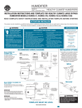
PLUMBING THE SADDLE VALVE
Hot or cold water, either hard or softened, can be used in the
humidifier.
1. Use the self-piercing saddle valve (included) to tap into
the water supply line at an appropriate location.
IMPORTANT
The saddle valve is not designed to regulate water
flow. The valve is either open or closed.
To prevent debris from clogging the solenoid inline
filter, be sure to install the saddle valve handle
pointing toward the ceiling.
NOTE: Lightly clean the copper tubing ends with fine
sandpaper before making any connections.
2. Use 1/4 in. O.D. copper tubing and connect the saddle
valve to the inlet side of the solenoid valve.
CAUTION
Hazardous Voltage.
Can cause personal injury or equipment damage.
Do not use any line connected to an air conditioner.
a. Place the brass compression nut over the copper
tubing.
NOTE: Do not over tighten the compression nut.
Moderate tightness prevents leaking.
b. Slide the brass ferrule over the tubing.
c. Insert the tubing into the solenoid valve fitting and
support the valve while tightening the
compression nut.
3. Connect a 1/2 in. (13 mm) drain tube to the humidifier
drain fitting and run to a suitable drain.
NOTE: Slope the drain tube downward for correct
drainage.
CHECKING THE INSTALLATION
Use the following procedure to check out the humidifier
installation:
1. Open the saddle valve.
2. Set the thermostat setpoint to 10°F (6°C) above the
room temperature.
NOTE: The furnace blower must be on for the
humidifier to operate.
3. Set the Convertible Humidity Control to a high setting,
or place the H1008A Automatic Humidity Control in the
Test position.
4. Observe the water running out of the drain line to be
sure the humidifier is working.
5. Check for leaks.
6. Reset the thermostat and Convertible Humidity Control
to a comfortable setting, or the Automatic Humidity
Control to the desired frost factor setting, for automatic
operation.
OPERATING THE HUMIDIFIER
The HE225A and HE265A
Humidifiers are controlled by
the Convertible Humidity
Control that is installed either
on an interior wall in the living
area or on the return air duct.
Choose the humidity control
setting using the combination
relative humidity/outdoor
temperature setting scale on the
humidity control dial. Match the
dial setting to the outdoor temperature for optimizing the
humidity level while reducing the moisture condensation on
inside windows. Table 5 can also be used to adjust the
humidity control to the recommended setting.
NOTE: As the outside temperature drops, the
recommended setting is lowered to accommodate
the effects of dewpoint. These settings should
reduce the accumulation of moisture and ice on the
windows and in other areas of the house.
Some indoor activities such as cooking, showering and
clothes drying can cause excessive levels of humidity and
start the accumulation of moisture on the windows.
NOTE: If this condition persists for more than a few hours,
set the humidity control to the lowest setting to turn
off the humidifier. If the condition does not improve,
ventilate your home to remove the moisture.
The Enviracaire Elite HE225B
and HE265B Humidifiers are
controlled by the Honeywell
H1008A Automatic Humidity
Control with HumidiCalc+
Software. The automatic
humidity control is mounted in
the return air duct where it can be
exposed to the air stream of the
return air. The HumidiCalc+ Software
inside the automatic humidity control
is designed to automatically adjust the humidity level based
on indoor temperature and humidity, inferred or measured
outdoor temperature, and the setting of the frost factor dial.
The frost factor allows for variations in furnace size, window
insulation and average daily climate temperature.
The Automatic Humidity Control with HumidiCalc+ Software
requires an initial adjustment period. Set the frost factor dial
on 5 and use Table 6 to adjust the frost factor—only one
setting at a time—increasing the dial setting for more
humidity, or reducing the setting if moisture develops on
inside windows. For more precise humidity adjustment, set
the frost factor between dial settings. Allow two days for the
humidity level to subside before making further adjustments.
Once the proper setting has been found, no further
adjustment is needed. HumidiCalc+ Software takes over
and makes any future adjustments caused by varying outdoor
temperatures, thus reducing moisture build-up on windows
while maintaining the optimal humidity level.
M12817
H1008A
H
um
id
ity C
o
ntro
l
Ré
gula
teur d
'hum
idit
é
-
2
0
°
F
-1
0
°
F
0
°
F
+
1
0
°
F
+
2
0
°
F
O
v
e
r
2
0
°
F
1
5
%
2
0
%
2
5
%
3
0
%
3
5
%
4
0
%
H
U
M
I
D
I
T
Y
S
E
T
T
I
N
G
O
U
T
D
O
O
R
T
E
M
P
E
R
A
T
U
R
E
-
3
0
°
C
-2
5
°
C
-
2
0
°
C
-
1
0
°
C
-
5
°
C
O
v
e
r
0
°
C
M14694
H8908A
HE225A,B AND HE265A,B BYPASS FLOW-THROUGH HUMIDIFIER
68-0244
6
Table 5. Recommended Convertible Humidity Control Settings.
Humidity Level Recommended Adjustment
Insufficient humidity Increase the frost factor dial by one setting.
Condensation on windows Decrease the frost factor dial by one setting.
At Outside Temperature Recommended Setting At Outside Temperature Recommended Setting
-20°F (-29°C) 15 +10°F (-12°C) 30
-10°F (-23°C) 20 +20°F (-7°C) 35
0°F (-18°C) 25 Above 20°F (-7°C) 40
Table 6. Recommended Frost Factor Settings.
OPERATION
The HE225A,B and HE265A,B Humidifiers use the principle
that vapor (evaporated water) is created when warm air blows
over a water soaked area. As the vapor circulates, the relative
humidity rises.
The humidity control monitors the relative humidity and
activates the humidifier accordingly. The humidifier has a
water supply that disburses water over an antimicrobial
humidifier pad. The warm dry air from the furnace passes
over the humidifier pad and collects moisture and them
circulates it through the house.
Humidified air feels warmer and more comfortable so the
homeowner may be able to lower the thermostat heating
setpoint and save money on heating fuel bills. The end result
is that the humidifier gives the homeowner a comfortable
environment that is also energy efficient.
MAINTENANCE
A regular maintenance program prolongs the life of the
humidifier and provides a more comfortable environment.
Either hard or soft water can be used in the humidifier.
Frequency of cleaning depends on the condition of the water.
CAUTION
Voltage Hazard.
Can cause electrical shock and equipment
damage.
Disconnect power supply before installing or
servicing.
IMPORTANT
Never oil any part of the humidifier.
Every 1 to 3 Months
(Depending on Water Quality)
Use the following procedure to clean the humidifier:
1. Disconnect the power and turn off the humidifier water
supply.
2. Remove the humidifier cover. See Fig. 5.
Fig. 5. Location of humidifier parts.
3. Remove the humidifier pad assembly from the
humidifier by grasping the tray and pulling it toward
you.
4. Pull one side of the humidifier pad assembly frame
toward you and remove the tray from the frame.
5. Gently pinch the water nozzle catches inward until the
water nozzle can be lifted off the tray.
6. Slide the antimicrobial humidifier pad out of the frame.
7. Carefully scrape any mineral deposits from the tray and
frame. Be sure the frame drain hole has nothing
blocking it.
M14672
WATER
FEED NOZZLE
FRAME
HUMIDIFIER
HOUSING
WATER
FEED TUBE
HUMIDIFIER
PAD ASSEMBLY
COVER
SIDEWALL
BY-PASS SIDEWALL
HE225A,B AND HE265A,B BYPASS FLOW-THROUGH HUMIDIFIER
68-0244
7
8. Check the humidifier pad and if excessive mineral
deposits are present, replace with a new antimicrobial
pad.
9. Disconnect the tube from the drain fitting on the bottom
of the humidifier housing.
10. Clean the drain fitting, if necessary.
11. Bend the drain tube to loosen any mineral deposits.
12. Flush the drain tube with pressurized water (a running
tap) to clean the tube.
13. Reattach the drain tube to the drain fitting.
14. Slide the humidifier pad back into the frame.
IMPORTANT
To maintain the antimicrobial properties of the
humidifier, use only a Honeywell HC22E or HC26E
Antimicrobial Pad. See Table 8 List of Replacement
Parts for appropriate pad. Be sure the marked side
of the antimicrobial humidifier pad is facing up for
proper performance.
15. Snap the water nozzle back on the tray.
16. Reattach the tray to the frame.
17. Place the humidifier pad assembly in the humidifier
housing and press until the assembly is completely
seated. Be careful not to pinch or kink the water feed
tube.
18. Replace the humidifier cover.
19. Verify the humidifier operation by following the steps in
the Checkout Procedure section.
End of Humidification Season
At the end of the heating season, follow steps 1 through 18
from the Every 1 To 3 Months section to clean the humidifier
and shut if off.
IMPORTANT
Be sure the humidifier power is off.
Beginning of Humidification Season
Refer to the Checkout Procedure section to complete the
humidifier startup.
Vacation
When leaving on vacation, turn off the humidifier water supply
and the humidity control. When returning from vacation, turn
on the humidifier water supply and reset the humidity control
to restart the humidifier.
CHECKOUT PROCEDURE
After winter startup or servicing, use the following procedure
to check the humidifier operation:
1. Turn on the humidifier power and water supply.
2. Turn the Convertible Humidity Control to the highest
setting, or place the H1008A Automatic Humidity
Control in the Test position and set the thermostat to
10°F (6°C) above the room temperature.
3. Observe that water is flowing out of the drain hose.
NOTE: The furnace blower must be on for the
humidifier to operate.
4. Reset the thermostat and Convertible Humidity Control
to a comfortable setting, or the H1008A Automatic
Humidity Control to the desired frost factor setting, for
automatic operation.
TROUBLESHOOTING
Refer to Table 7 for troubleshooting procedures.
Problem What To Look For What To Do
Low humidity Furnace blower not operating Reset circuit breaker or check for blown fuse.
Check that the furnace power is on.
Check all external wiring connections.
Check the humidity control setting.
Call a professional heating contractor.
Rapid air changes. Drafts (cold air
is dry and is an added load to the
humidifier).
Keep doors and windows closed.
Close fireplace damper when not in use.
Keep exhaust fan running time to a minimum.
Seal around doors and windows.
High humidity Condensation on walls. Turn humidity control and water off until condensation is
completely evaporated.
Heavy condensation on windows. Turn humidity control down low enough to eliminate
condensation caused by moisture from bathing, mopping,
cooking, etc. If moisture persists, more ventilation is needed.
Table 7. Troubleshooting Procedures.
HE225A,B AND HE265A,B BYPASS FLOW-THROUGH HUMIDIFIER
68-0244
8
M14820
9
10
11
3
6
7
5
4
8
1
2
13
12
8
8
4
0
3
0
2
0
10
5
0
6
0
OFF
ON
REPLACEMENT PARTS
Refer to Fig. 6 and Table 8 when ordering replacement parts.
Fig. 6. Exploded view of humidifier parts.
HE225A,B AND HE265A,B BYPASS FLOW-THROUGH HUMIDIFIER
68-0244
9
Table 8. List Of Replacement Parts For HE220A,B, HE260A,B Humidifiers.
Exploded
View Number Description HE225 Part Number HE265 Part Number
1 Side wall 32001612-002 32001626-002
2 Bypass side wall 32001613-002 32001627-002
3 Cover Assembly 32001611-003 32001611-004
4 PerfectFlo™ water distribution tray 32001619-001 32001630-001
5 Antimicrobial humidifier pad HC22E1003 HC26E1004
6 Frame 32001621-001 32001632-001
7 Drain fitting 32001615-001 32001615-001
8 Solenoid valve assembly
(includes water feed tube and nozzle)
32001639-002 32001639-002
9 Saddle valve assembly 32001616-001 32001616-001
10 Transformer (10 VA) 32001652-001 32001652-001
11 Convertible Humidity Control H8908B1002 H8908B1002
12 Automatic Humidity control with
HumidiCalc™+ Software
H1008A1008 H1008A1008
13 Base insert assembly, includes no. 8 above 32001625-003 32001625-004
Hardware Kit for Solenoid Assembly (same as Solenoid
valve assembly without the solenoid valve)
32001752-001 32001752-001
Current Sensing Relay 32001754-001 32001754-001
HE225A,B AND HE265A,B BYPASS FLOW-THROUGH HUMIDIFIER
68-0244
10
HE225A,B AND HE265A,B BYPASS FLOW-THROUGH HUMIDIFIER
68-0244
11
HE225A,B AND HE265A,B BYPASS FLOW-THROUGH HUMIDIFIER
68-0244
12
Home and Building Control
Honeywell Limited-Honeywell Limitée
35 Dynamic Drive
Scarborough, Ontario
M1V 4Z9
Home and Building Control
Honeywell
1985 Douglas Drive North
Golden Valley, MN 55422
Printed in U.S.A. on recycled
paper containing at least 10%
post-consumer paper fibers.
68-0244 G.H. 11-00 www.honeywell.com/yourhome/
ULTRAVIOLET AIR TREATMENT SYSTEM
F300E ELECTRONIC AIR CLEANER
ENVIRACAIRE ELITE HUMIDIFIERS
ZAP airborne germs.
Kill most germs before they recycle
through your home.
Prevent mold spores from growing on your
system cooling coils.
TRAP airborne particles.
Up to 99% efficient at capturing
airborne particles.
Effectively REDUCES fungi, bacteria,
mold antigen, cat antigen and ragweed
pollen antigen that pass through system.
Moisturize parched air.
Help maintain proper humidity to minimize
adverse health effects.
Features special antimicrobial agent to prevent
surface growth and migration of bacteria, mold,
fungus and algae on the humidifier pad.
M14757
Honeywell offers one of the broadest families of home solutions in the
industry - ranging from thermostats, zoning, ventilation, air cleaning,
humidification to internet-enabled home control and wireless
WebPAD™ devices for web surfing and more!! Check out our offerings on-line at www.honeywell.com/yourhome
/
... only from Honeywell.
IMPROVE YOUR INDOOR AIR WITH A COMPLETE
whole-house air quality system
  • Page 1 1
  • Page 2 2
  • Page 3 3
  • Page 4 4
  • Page 5 5
  • Page 6 6
  • Page 7 7
  • Page 8 8
  • Page 9 9
  • Page 10 10
  • Page 11 11
  • Page 12 12

Honeywell HE265A User manual

Category
Fireplaces
Type
User manual

Ask a question and I''ll find the answer in the document

Finding information in a document is now easier with AI