Aprilaire 400M Application Manual

Type
Application Manual

Aprilaire 400M is a bypass humidifier designed for smaller homes, featuring a 0.7 GPH water usage rate and a compact size of 15-5/8W x 13H x 10-1/4D inches. It operates on 24V-60Hz power with a 0.5 AMP draw and is equipped with a built-in humidistat for automatic humidity control. The 400M is suitable for use with gas or electric heat, and can be installed on either the supply or return plenum. To maximize performance, it can be plumbed to hot water (up to 140°F) and paired with a blower activation feature for enhanced humidification.

Aprilaire 400M is a bypass humidifier designed for smaller homes, featuring a 0.7 GPH water usage rate and a compact size of 15-5/8W x 13H x 10-1/4D inches. It operates on 24V-60Hz power with a 0.5 AMP draw and is equipped with a built-in humidistat for automatic humidity control. The 400M is suitable for use with gas or electric heat, and can be installed on either the supply or return plenum. To maximize performance, it can be plumbed to hot water (up to 140°F) and paired with a blower activation feature for enhanced humidification.

Humidifier Application Guide
Page Application
Plenum
Temperature (°F)
Recommended
Model Series Control
Automatic Manual
3
Gas or Electric
Heat
Air Handling Unit
with accessible
supply and return
plenums
120-140 400, 500, 600,700, 800 60, 62, 8910, 8620
65, 4655 with model
50 or 4851
6 Boiler 120-140 400, 500, 600,700, 800 60, 62, 8910, 8620
65, 4655 with model
50 or 4851
9 Heat Pump 90-100 400, 500, 600,700, 800 60, 62, 8910, 8620
65, 4655 with model
50 or 4851
12 Air Conditioning Below 90
800 and 800 with 850
Fan Pack
62, 8910, 8620
65, 4655 with 4851
and 8024
15
No forced air
system
800 with 850 Fan Pack 8910, 8620 65, 4655
16
Air Handling Unit
with no return duct
700, 800 60, 62, 8910, 8620
65, 4655 with model
50 or 4851
19
Alternate
configurations and
wiring diagrams
400, 500, 600, 700, 800 60, 62
ITEMS NOT FURNISHED TOOLS NEEDED
Mounting screws (sheet metal screws)
Water supply line (1/4” OD copper)
18AWG low voltage wire
Bypass duct (bypass units only)
Model 50 or 4851 relays (to be used with manual humidistats only)
*See Installation Instructions for more information
Note:
Do not install where freezing temperatures can occur.
Installation must be done by qualified contractor.
Installations must conform to local codes.
1/2” and 7/16” combination wrench
1/8” by 2” flathead screw driver
Tin snips
Wire stripper
Aprilaire
®
humidifiers can be installed on many different types of HVAC equipment and controlled to provide optimum humidity levels for each
application. This Application Guide is to assist installers in selecting which Aprilaire humidifier is appropriate for a particular application and
how to configure the controls to deliver optimum humidity.
To use this guide, select the application (type of HVAC equipment) and humidifier model then turn to the appropriate reference page. The
reference pages will give you guidelines for installation, when and how to use blower activation, and how to connect third party controls.
APRILAIRE
®
HUMIDIFIER SPECIFICATIONS
HUMIDIFIER SIZING CHART (8’ CEILINGS)
A. Unit Size (inches)
B. Plenum Opening (inches)
Capacity
gpd = gallons per day Electical Data
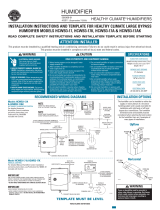
Model 700*/700M**
Powered Unit – Built-in fan that pulls
heated air directly from the furnace.
A. 15-29/32W x 18H x 10-11/32D
B. 14-3/4W x 14-5/16H
18 gpd 120V-60Hz
0.8 AMP
Model 600*/600M**
Bypass Unit – Uses the furnace blower to
move air through a Water Panel
®
.
A. 15-3/8W x 15-3/4H x 10-1/4D
6” dia. round opening
B. 10W x 12-3/4H
17 gpd 24V-60Hz
0.5 AMP
Model 400*/400M**
Bypass Unit – Uses 100% of water and
evaporative technology that eliminates the
need for a drain.
A. 15-3/8W x 15-3/4H x 10-1/4D
6” dia. round opening
B. 10W x 12-3/4H
17 gpd 24V-60Hz
0.5 AMP
Model 500*/500M**
Bypass Unit – Designed for smaller homes.
A. 15-5/8W x 13H x 10-1/4D
6” dia. round opening
B. 9-1/2W x 9-1/2H
12 gpd 24V-60Hz
0.5 AMP
Model 800
Steam Humidifier – For applications when
evaporative units are less practical (attics,
crawl spaces, closets, milder winter
climates, non-forced air heating source).
A. 10-1/8W x 20-7/8H x 7-1/8D
B. N/A
11.5 gpd
16.0 gpd
120V-60Hz
11.5 amp
16 amp
20.5 gpd
30.0 gpd
208V-60Hz
11.5 amp
16 amp
23.3 gpd
34.6 gpd
240V-60Hz
11.5 amp
16 amp
* = Automatic Digital Control (shown)
** = Manual Control – For those rare occurrences where an automatic control is not practical, Aprilaire digital control can be installed in manual mode while still delivering the accuracy and
information you need for optimum performance.
Warranty – All Aprilaire models are warranted for five (5) years from date of installation for parts.
Heat pumpsPlumbing the humidifier to hot water is recommended on all heat pump installations or if it is installed to operate independently of a call for heat.
Bypass humidifiers can be installed on the supply or return plenum.
Water usage rate – Model 700: 6GPH; Models 500, 600: 3GPH; Model 400: 0.7GPH; Model 800: 0.6 –1.8GPH depending on voltage, amp draw and water quality.
House Size 1000 ft
2
1500 ft
2
2000 ft
2
2500 ft
2
3000 ft
2
4000 ft
2
5000 ft
2
Structural Tightness Humidity needed (GPD per AHRI)*** Guideline F
Tight 4.3 6.4 8.5 10.6 12.7 17 21.2
Average 8.6 12.8 17 21.3 25.4 34 42.6
Loose 12.7 19.1 25.5 31.8 38.1 51 63.6
*** = AHRI Air Conditioning, Heating, and Refrigeration Institute GPD = Gallons Per Day Guideline F
• A family of 4 will add 2 gallons of humidity per day through everyday activities like breathing, cooking, bathing and washing.
• Evaporative capacities assume blower is active 100% of the time, plenum temperature is at 120˚F and water is cold.
WARRANTY
YEAR
FIVE
2
GAS OR ELECTRIC FURNACE – AIR HANDLING UNIT WITH
ACCESSIBLE SUPPLY AND RETURN PLENUMS
Recommended Series: 400, 500, 600, 700, 800
Plenum Temperature
Gas and electric furnaces typically have plenum temperatures between 120 and 140°F which will maximize the evaporation process during a
heat call. To optimize the performance of your evaporative humidifier, use blower activation in conjunction with HOT water.
Inlet Water Temperature
Hot or cold water can be used with evaporative humidifiers. To maximize evaporative performance plumb to HOT Water (140°F Max) and use
Blower Activation.
The Model 700 series Fan Powered Humidifier must be plumbed to HOT water when installed on a return duct.
Model 400 Water Saving Humidifier can be plumbed to HOT water but the benefit is minimal.
Model 800 Steam Humidifier MUST be plumbed to COLD water only.
Variable Speed Blowers
The more HOT air delivered to the humidifier, the more humidity is delivered into the air stream. Systems with low continuous fan speeds will
have reduced evaporation or absorption unless the fan speed setting is increased. Set the continuous fan speed to approximately the same
speed as a heat call setting.
Plumbing evaporative humidifiers to HOT water can increase evaporation at low fan speeds.
Blower Activation
The Blower Activation feature on Model 60 and 62 humidifier controls will sample the household air if the HVAC system has been idle for
one hour and will energize the HVAC fan to allow the humidifier to run for two hours or until the desired humidity level is reached, whichever
comes first. If humidity levels are not reached during a normal heating call, the Blower Activation feature will extend the blower call for two
hours or until the humidity call is satisfied, whichever comes first.
When using Blower Activation, plumb evaporative humidifier to HOT water. The Model 800 Steam Humidifier must be plumbed to COLD water
only, in order to temper drain water.
The Blower Activation Relay (Model 4851) will activate the HVAC blower on a call for humidity when used in conjunction with a manual
humidistat; plumb evaporative humidifiers to HOT water.
Third Party Controls
All current Aprilaire controls use a dry contact to switch 24VAC on and off. Ensure that third party controls are applied in the same manner. If a
third party control provides 24VAC (10VA minimum) do not use the included 10VA transformer when installing evaporative humidifiers.
The Model 800 supplies 24VAC internally. If a third party control that supplies 24VAC is used with the Model 800, use an isolation relay to
switch power. DO NOT apply 24 VAC to the HUMIDISTAT terminals.
3
TYPICAL HUMIDIFIER MOUNTING CONFIGURATIONS
90-1079
90-1519
RETURN
RETURN
RETURN
SUPPLY
SUPPLY
SUPPLY
RETURN
RETURN
RETURN
SUPPLY
SUPPLY
SUPPLY
RETURN
RETURN
RETURN
SUPPLY
SUPPLY
SUPPLY
16" for
Steam
Hose
30" for
Service
Access
16" for
Electrical
Access
4"
16"
for Drain
FRONT VIEW
SIDE VIEW
BYPASS HUMIDIFIERS
FAN POWERED HUMIDIFIER STEAM HUMIDIFIER
DO NOT install series 700 humidifiers on horizontal duct runs.
Recommended Plumb to hot water if
mounted on return duct.
Series 700 mounted
with AC “A” coil
90-921
4
TYPICAL WIRING DIAGRAMS – GAS OR ELECTRIC HEAT
MANUAL HUMIDIFIER CONTROL WIRING
MANUAL CONTROL
WITH BLOWER ACTIVATION WIRING
AUTOMATIC DIGITAL HUMIDIFIER CONTROL
WITH MODEL 800 STEAM HUMIDIFIER
DIGITAL MANUAL CONTROL WIRING
AUTOMATIC DIGITAL CONTROL WIRING
HOME COMFORT CONTROL
WIRING
IAQ THERMOSTAT WIRED TO CONTROL A HUMIDIFIER
FURNACE
BLOWER MOTOR
MODEL 50
CURRENT
SENSING RELAY
(IF REQUIRED)
24 VAC FURNACE
ACCESSORY TERMINALS
OR TRANSFORMER
(10VA MINIMUM)
SHUT-OFF
(SADDLE VALVE)
WATER SUPPLY
YELLOW
24V SOLENOID
VALVE WIRES
IMPORTANT
USE 120 VAC POWER SOURCE OTHER THAN FURNACE MOTOR
CIRCUIT. HOWEVER, THE TRANSFORMER CAN BE POWERED
OFF THE HOT 120 VAC LINE BEFORE IT ENTERS THE FURNACE.
DO NOT WIRE TRANSFORMER INTO FURNACE BLOWER CIRCUIT.
IMPORTANT
WHEN MODEL 50 CURRENT SENSING RELAY IS USED:
WIRE MODEL 50 CURRENT SENSING RELAY INTO
24 VAC HUMIDIFIER CONTROL CIRCUIT ONLY!
DO NOT INSTALL IN TRANSFORMER PRIMARY CIRCUIT.
CONNECT DRAIN LINE HERE
COMMON
HI
LO
APRILAIRE
EVAPORATIVE
HUMIDIFIER
SOLENOID VALVE
CIRCUIT WIRES
MODEL 65 CONTROL
HVAC EQUIPMENT
24VAC
CONTINUOUSLY
POWERED
TRANSFORMER
COMMON
MOTOR
LEAD
HVAC BLOWER
MODEL 50
RELAY
APRILAIRE
HUMIDIFIER
TERMINALS FOR THE
MANUAL HUMIDIFIER CONTROL
(MHC)
TYPICAL 24 VAC
TERMINAL STRIP
IN FURNACE
THERMOSTAT
APRILAIRE
4851 RELAY
REMOVE WIRE
“G” TO “G”
BLUE (NC)
ORANGE (NO)
YELLOW (C)
500 & 600 SERIES
YELLOW WIRES
700 SERIES (GRAY)
BROWN WIRES
CONSTANT
24VAC
MIN. 10VA
CRWGY
YGWRC
WHITE/YELLOW
WHITE/BLUE
NOTE: 18AWG WIRE IS ACCEPTABLE
FOR 24V INSTALLATIONS.
NOTE: FOR MAXIMUM CAPACITY PLUMB
HUMIDIFIER TO HOT WATER WHEN USING
THIS WIRING CONFIGURATION.
YELLOW
WIRES
G
Y
W
C
R
THERMOSTAT
110 VAC
R
C
W
Y
G
FURNACE
OUTDOOR
TEMPERATURE
SENSOR FOR
AUTOMATIC
MODE
NORTH, EAST
OR WEST SIDE
OF HOME
ABOVE EXPECTED
SNOW LINE
CONTINUOUSLY POWERED
24 VAC TRANSFORMER
PROVIDED WITH HUMIDIFIER
CONNECT TO
HOT WATER SUPPLY
CONNECT DRAIN
LINE HERE
OUTPUTSINPUTSPOWER
GW
CRHHODT GfA
ADHC TERMINAL STRIP
B
24 VAC from HVAC
Equipment “R” & “C”
Communication with
Aprilaire 8570 Thermostat
Outdoor Temperature Sensor
Heat Signal from HVAC Equipment
Fan Signal from Thermostat
Fan Signal to HVAC Equipment
MODEL 62 DIGITAL HUMIDIFIER CONTROL
24V TERMINALS
OPTIONAL:
AIR FLOW PROVING SWITCH #4592
Connect 1/4" plastic tubing from H (High) side
of proving switch to the airflow sensing probe
located 1.5 duct diameters downstream of
blower. Leave L (Low) side open to amosphere.
OPTIONAL:
HIGH HUMIDITY LIMIT SWITCH #4594
Switch breaks C to NC connection when
measured RH is above setpoint RH.
HGf RCAB ODT GWH
FAN PACK HUMIDISTAT
C
NO
NC
C
NO
NC
THERMOSTAT
W
W2
W3
Y
Y2
Y3
G
HC HP
EQ
3
C
RC
RH
L
G
O
Y2
Y
B
W2
W
R
C
TRANSFORMER
TRANSFORMER
TRANSFORMER
TRANSFORMER
VNT
DH
HUM
EAC
DH
DH
no
com
nc
NOTE:
THE MODEL 800 STEAM HUMIDIFIER
IS POWERED INTERNALLY.
DO NOT
ADD A TRANSFORMER
2nd HEATING
1st HEATING
FAN
1
st COMPRESSOR
2nd COMPRESSOR
2
1
3rd HEATING
3nd COMPRESSOR
DEHUMIDIFIER
8120 DAMPER
PILOT RELAY FOR
120 V AC TO EAC
HUMIDIFIER
G
Y2
Y
O/B
I1
W
RC
R
W2
S2
L
C
S1
T1 T2
JUMPER
OUTDOOR TEMP
SENSOR
1st HEATING
1st COOLING
FAN
2nd HEATING
2nd COOLING
NOT USED
TRANSFORMER
REMOTE TEMP
SENSOR
NOT USED
I2
HUMIDIFIER
NOTE:
THE MODEL 800 STEAM HUMIDIFIER
IS POWERED INTERNALLY.
DO NOT
ADD A TRANSFORMER
90-1207
90-1407
90-1544
90-1822
90-1820
90-1510
90-1671
5
BOILER – AIR HANDLING UNIT
WITH ACCESSIBLE SUPPLY AND RETURN PLENUMS
Recommended Series: 400, 500, 600, 700, 800
Plenum Temperature
Boilers typically produce plenum temperatures between 120 and 140°F which will maximize the evaporation process during a heat call. To
optimize the performance of your evaporative humidifier, use Blower Activation in conjunction with HOT water. Mount humidifier or bypass
duct downstream of the hot water coil.
Inlet Water Temperature
Hot or cold water can be used with evaporative humidifiers. To maximize evaporative performance plumb to HOT Water (140°F Max) and use
Blower Activation.
The Model 700 series Fan Powered Humidifier must be plumbed to HOT water when installed on a return duct.
Model 400 Water Saving Humidifier can be plumbed to Hot water but the benefit is minimal.
Model 800 Steam Humidifier MUST be plumbed to COLD water only.
Variable Speed Blowers
The more HOT air delivered to the humidifier, the more humidity is delivered into the air stream. Systems with low continuous fan speeds will
have reduced evaporation or absorption unless the fan speed setting is increased. Set the continuous fan speed to approximately the same
speed as a heat call setting.
Plumbing evaporative humidifiers to HOT water can increase evaporation at low fan speeds.
Blower Activation
The Blower Activation feature on Model 60 and 62 humidifier controls will sample the household air if the HVAC system has been idle for
one hour and will energize the HVAC fan to allow the humidifier to run for two hours or until the desired humidity level is reached, whichever
comes first. If humidity levels are not reached during a normal heating call, the Blower Activation feature will extend the blower call for two
hours or until the humidity call is satisfied, whichever comes first.
When using Blower Activation, plumb evaporative humidifier to HOT water. The Model 800 Steam Humidifier must be plumbed to COLD water
only, in order to temper drain water.
The Blower Activation Relay (Model 4851) will activate the HVAC blower on a call for humidity when used in conjunction with a manual
humidistat; plumb evaporative humidifiers to HOT water.
Third Party Controls
All current Aprilaire controls use a dry contact to switch 24VAC on and off. Ensure that third party controls are applied in the same manner. If a
third party control provides 24VAC (10VA minimum) do not use the included 10VA transformer when installing evaporative humidifiers.
The Model 800 supplies 24VAC internally. If a third party control that supplies 24VAC is used with the Model 800, use an isolation relay to
switch power. DO NOT apply 24 VAC to the HUMIDISTAT terminals.
6
TYPICAL HUMIDIFIER MOUNTING CONFIGURATIONS
90-1079
90-1519
RETURN
RETURN
RETURN
SUPPLY
SUPPLY
SUPPLY
RETURN
RETURN
RETURN
SUPPLY
SUPPLY
SUPPLY
RETURN
RETURN
RETURN
SUPPLY
SUPPLY
SUPPLY
16" for
Steam
Hose
30" for
Service
Access
16" for
Electrical
Access
4"
16"
for Drain
FRONT VIEW
SIDE VIEW
BYPASS HUMIDIFIERS
STEAM HUMIDIFIERFAN POWERED HUMIDIFIER
Series 700 mounted
with AC “A” coil
DO NOT install series 700 humidifiers on horizontal duct runs.
Recommended Plumb to hot water if
mounted on return duct.
90-921
7
TYPICAL WIRING DIAGRAMS – BOILER
MANUAL HUMIDIFIER CONTROL WIRING
MANUAL CONTROL
WITH BLOWER ACTIVATION WIRING
AUTOMATIC DIGITAL HUMIDIFIER CONTROL
WITH MODEL 800 STEAM HUMIDIFIER
DIGITAL MANUAL CONTROL WIRING
AUTOMATIC DIGITAL CONTROL WIRING
HOME COMFORT CONTROL
WIRING
IAQ THERMOSTAT WIRED TO CONTROL A HUMIDIFIER
FURNACE
BLOWER MOTOR
MODEL 50
CURRENT
SENSING RELAY
(IF REQUIRED)
24 VAC FURNACE
ACCESSORY TERMINALS
OR TRANSFORMER
(10VA MINIMUM)
SHUT-OFF
(SADDLE VALVE)
WATER SUPPLY
YELLOW
24V SOLENOID
VALVE WIRES
IMPORTANT
USE 120 VAC POWER SOURCE OTHER THAN FURNACE MOTOR
CIRCUIT. HOWEVER, THE TRANSFORMER CAN BE POWERED
OFF THE HOT 120 VAC LINE BEFORE IT ENTERS THE FURNACE.
DO NOT WIRE TRANSFORMER INTO FURNACE BLOWER CIRCUIT.
IMPORTANT
WHEN MODEL 50 CURRENT SENSING RELAY IS USED:
WIRE MODEL 50 CURRENT SENSING RELAY INTO
24 VAC HUMIDIFIER CONTROL CIRCUIT ONLY!
DO NOT INSTALL IN TRANSFORMER PRIMARY CIRCUIT.
CONNECT DRAIN LINE HERE
COMMON
HI
LO
APRILAIRE
EVAPORATIVE
HUMIDIFIER
SOLENOID VALVE
CIRCUIT WIRES
MODEL 65 CONTROL
HVAC EQUIPMENT
24VAC
CONTINUOUSLY
POWERED
TRANSFORMER
COMMON
MOTOR
LEAD
HVAC BLOWER
MODEL 50
RELAY
APRILAIRE
HUMIDIFIER
TERMINALS FOR THE
MANUAL HUMIDIFIER CONTROL
(MHC)
TYPICAL 24 VAC
TERMINAL STRIP
IN FURNACE
THERMOSTAT
APRILAIRE
4851 RELAY
REMOVE WIRE
“G” TO “G”
BLUE (NC)
ORANGE (NO)
YELLOW (C)
500 & 600 SERIES
YELLOW WIRES
700 SERIES (GRAY)
BROWN WIRES
CONSTANT
24VAC
MIN. 10VA
CRWGY
YGWRC
WHITE/YELLOW
WHITE/BLUE
NOTE: 18AWG WIRE IS ACCEPTABLE
FOR 24V INSTALLATIONS.
NOTE: FOR MAXIMUM CAPACITY PLUMB
HUMIDIFIER TO HOT WATER WHEN USING
THIS WIRING CONFIGURATION.
YELLOW
WIRES
G
Y
W
C
R
THERMOSTAT
110 VAC
R
C
W
Y
G
FURNACE
OUTDOOR
TEMPERATURE
SENSOR FOR
AUTOMATIC
MODE
NORTH, EAST
OR WEST SIDE
OF HOME
ABOVE EXPECTED
SNOW LINE
CONTINUOUSLY POWERED
24 VAC TRANSFORMER
PROVIDED WITH HUMIDIFIER
CONNECT TO
HOT WATER SUPPLY
CONNECT DRAIN
LINE HERE
OUTPUTSINPUTSPOWER
GW
CRHHODT GfA
ADHC TERMINAL STRIP
B
24 VAC from HVAC
Equipment “R” & “C”
Communication with
Aprilaire 8570 Thermostat
Outdoor Temperature Sensor
Heat Signal from HVAC Equipment
Fan Signal from Thermostat
Fan Signal to HVAC Equipment
MODEL 62 DIGITAL HUMIDIFIER CONTROL
24V TERMINALS
OPTIONAL:
AIR FLOW PROVING SWITCH #4592
Connect 1/4" plastic tubing from H (High) side
of proving switch to the airflow sensing probe
located 1.5 duct diameters downstream of
blower. Leave L (Low) side open to amosphere.
OPTIONAL:
HIGH HUMIDITY LIMIT SWITCH #4594
Switch breaks C to NC connection when
measured RH is above setpoint RH.
HGf RCAB ODT GWH
FAN PACK HUMIDISTAT
C
NO
NC
C
NO
NC
THERMOSTAT
W
W2
W3
Y
Y2
Y3
G
HC HP
EQ
3
C
RC
RH
L
G
O
Y2
Y
B
W2
W
R
C
TRANSFORMER
TRANSFORMER
TRANSFORMER
TRANSFORMER
VNT
DH
HUM
EAC
DH
DH
no
com
nc
NOTE:
THE MODEL 800 STEAM HUMIDIFIER
IS POWERED INTERNALLY.
DO NOT
ADD A TRANSFORMER
2nd HEATING
1st HEATING
FAN
1
st COMPRESSOR
2nd COMPRESSOR
2
1
3rd HEATING
3nd COMPRESSOR
DEHUMIDIFIER
8120 DAMPER
PILOT RELAY FOR
120 V AC TO EAC
HUMIDIFIER
G
Y2
Y
O/B
I1
W
RC
R
W2
S2
L
C
S1
T1 T2
JUMPER
OUTDOOR TEMP
SENSOR
1st HEATING
1st COOLING
FAN
2nd HEATING
2nd COOLING
NOT USED
TRANSFORMER
REMOTE TEMP
SENSOR
NOT USED
I2
HUMIDIFIER
NOTE:
THE MODEL 800 STEAM HUMIDIFIER
IS POWERED INTERNALLY.
DO NOT
ADD A TRANSFORMER
90-1207
90-1407
90-1544
90-1822
90-1820
90-1510
90-1671
8
HEAT PUMP – AIR HANDLING UNIT
WITH ACCESSIBLE SUPPLY AND RETURN PLENUMS
Recommended Series: 400, 500, 600, 700, 800
Plenum Temperature
Heat pumps typically have plenum temperatures between 90 and 100°F which require HOT water to aid in the evaporation process. Using
Blower Activation will help maintain humidity levels in the home. Series 400 Humidifiers will perform at reduced capacity due to lower plenum
temperatures.
Inlet Water Temperature
To maximize evaporative performance plumb to HOT Water (140°F Max) and use Blower Activation.
The Model 700 series Fan Powered Humidifier must be plumbed to HOT water when installed on a return duct.
Model 400 Water Saving Humidifier can be plumbed to Hot water but the benefit is minimal.
Model 800 Steam humidifier MUST be plumbed to COLD water only.
Variable Speed Blowers
The more HOT air delivered to the humidifier, the more humidity is delivered into the air stream. Systems with low continuous fan speeds will
have reduced evaporation or absorption unless the fan speed setting is increased. Set the continuous fan speed to approximately the same
speed as a heat call setting.
Plumbing evaporative humidifiers to HOT water can increase evaporation at low fan speeds.
Blower Activation
The Blower Activation feature on Model 60 and 62 humidifier controls will sample the household air if the HVAC system has been idle for
one hour and will energize the HVAC fan to allow the humidifier to run for two hours or until the desired humidity level is reached, whichever
comes first. If humidity levels are not reached during a normal heating call, the Blower Activation feature will extend the blower call for two
hours or until the humidity call is satisfied, whichever comes first.
When using Blower Activation, plumb evaporative humidifier to HOT water. The Model 800 Steam Humidifier must be plumbed to COLD water
only, in order to temper drain water.
The Blower Activation Relay (Model 4851) will activate the HVAC blower on a call for humidity when used in conjunction with a manual
humidistat; plumb evaporative humidifiers to HOT water.
Third Party Controls
All current Aprilaire controls use a dry contact to switch 24VAC on and off. Ensure that third party controls are applied in the same manner. If a
third party control provides 24VAC (10VA minimum) do not use the included 10VA transformer when installing evaporative humidifiers.
The Model 800 supplies 24VAC internally. If a third party control that supplies 24VAC is used with the Model 800, use an isolation relay to
switch power. DO NOT apply 24 VAC to the HUMIDISTAT terminals.
9
TYPICAL HUMIDIFIER MOUNTING CONFIGURATIONS
90-1079
90-151990-921
RETURN
RETURN
RETURN
SUPPLY
SUPPLY
SUPPLY
RETURN
RETURN
RETURN
SUPPLY
SUPPLY
SUPPLY
RETURN
RETURN
RETURN
SUPPLY
SUPPLY
SUPPLY
16" for
Steam
Hose
30" for
Service
Access
16" for
Electrical
Access
4"
16"
for Drain
FRONT VIEW
SIDE VIEW
BYPASS HUMIDIFIERS
FAN POWERED HUMIDIFIER STEAM HUMIDIFIER
10
TYPICAL WIRING DIAGRAMS – HEAT PUMP
MANUAL HUMIDIFIER CONTROL WIRING
MANUAL CONTROL
WITH BLOWER ACTIVATION WIRING
AUTOMATIC DIGITAL HUMIDIFIER CONTROL
WITH MODEL 800 STEAM HUMIDIFIER
DIGITAL MANUAL CONTROL WIRING
AUTOMATIC DIGITAL CONTROL WIRING
HOME COMFORT CONTROL
WIRING
IAQ THERMOSTAT WIRED TO CONTROL A HUMIDIFIER
FURNACE
BLOWER MOTOR
MODEL 50
CURRENT
SENSING RELAY
(IF REQUIRED)
24 VAC FURNACE
ACCESSORY TERMINALS
OR TRANSFORMER
(10VA MINIMUM)
SHUT-OFF
(SADDLE VALVE)
WATER SUPPLY
YELLOW
24V SOLENOID
VALVE WIRES
IMPORTANT
USE 120 VAC POWER SOURCE OTHER THAN FURNACE MOTOR
CIRCUIT. HOWEVER, THE TRANSFORMER CAN BE POWERED
OFF THE HOT 120 VAC LINE BEFORE IT ENTERS THE FURNACE.
DO NOT WIRE TRANSFORMER INTO FURNACE BLOWER CIRCUIT.
IMPORTANT
WHEN MODEL 50 CURRENT SENSING RELAY IS USED:
WIRE MODEL 50 CURRENT SENSING RELAY INTO
24 VAC HUMIDIFIER CONTROL CIRCUIT ONLY!
DO NOT INSTALL IN TRANSFORMER PRIMARY CIRCUIT.
CONNECT DRAIN LINE HERE
COMMON
HI
LO
APRILAIRE
EVAPORATIVE
HUMIDIFIER
SOLENOID VALVE
CIRCUIT WIRES
MODEL 65 CONTROL
HVAC EQUIPMENT
24VAC
CONTINUOUSLY
POWERED
TRANSFORMER
COMMON
MOTOR
LEAD
HVAC BLOWER
MODEL 50
RELAY
APRILAIRE
HUMIDIFIER
TERMINALS FOR THE
MANUAL HUMIDIFIER CONTROL
(MHC)
TYPICAL 24 VAC
TERMINAL STRIP
IN FURNACE
THERMOSTAT
APRILAIRE
4851 RELAY
REMOVE WIRE
“G” TO “G”
BLUE (NC)
ORANGE (NO)
YELLOW (C)
500 & 600 SERIES
YELLOW WIRES
700 SERIES (GRAY)
BROWN WIRES
CONSTANT
24VAC
MIN. 10VA
CRWGY
YGWRC
WHITE/YELLOW
WHITE/BLUE
NOTE: 18AWG WIRE IS ACCEPTABLE
FOR 24V INSTALLATIONS.
NOTE: FOR MAXIMUM CAPACITY PLUMB
HUMIDIFIER TO HOT WATER WHEN USING
THIS WIRING CONFIGURATION.
YELLOW
WIRES
G
Y
W
C
R
THERMOSTAT
110 VAC
R
C
W
Y
G
FURNACE
OUTDOOR
TEMPERATURE
SENSOR FOR
AUTOMATIC
MODE
NORTH, EAST
OR WEST SIDE
OF HOME
ABOVE EXPECTED
SNOW LINE
CONTINUOUSLY POWERED
24 VAC TRANSFORMER
PROVIDED WITH HUMIDIFIER
CONNECT TO
HOT WATER SUPPLY
CONNECT DRAIN
LINE HERE
OUTPUTSINPUTSPOWER
GW
CRHHODT GfA
ADHC TERMINAL STRIP
B
24 VAC from HVAC
Equipment “R” & “C”
Communication with
Aprilaire 8570 Thermostat
Outdoor Temperature Sensor
Heat Signal from HVAC Equipment
Fan Signal from Thermostat
Fan Signal to HVAC Equipment
MODEL 62 DIGITAL HUMIDIFIER CONTROL
24V TERMINALS
OPTIONAL:
AIR FLOW PROVING SWITCH #4592
Connect 1/4" plastic tubing from H (High) side
of proving switch to the airflow sensing probe
located 1.5 duct diameters downstream of
blower. Leave L (Low) side open to amosphere.
OPTIONAL:
HIGH HUMIDITY LIMIT SWITCH #4594
Switch breaks C to NC connection when
measured RH is above setpoint RH.
HGf RCAB ODT GWH
FAN PACK HUMIDISTAT
C
NO
NC
C
NO
NC
HEAT PUMP TRANSFORMER
C
R
W
W2
B
Y
Y2
O
G
L
RH
RC
C
3
EQ
HPHC
G
Y3
Y2
Y
W3
W2
W
THERMOSTAT
TRANSFORMER
TRANSFORMER
TRANSFORMER
VNT
DH
HUM
EAC
DH
DH
no
com
nc
NOTE:
THE MODEL 800 STEAM HUMIDIFIER
IS POWERED INTERNALLY.
DO NOT
ADD A TRANSFORMER
FAULT DETECT
REVERSING VALV E
REVERSING VALV E
1
2
2nd COMPRESSOR
1st COMPRESSOR
FAN
1st HEATING
2nd HEATING
DEHUMIDIFIER
8120 DAMPER
PILOT RELAY FOR
120 V AC TO EAC
HUMIDIFIER
2nd COMPRESSOR
2nd AUX HEATING
FAN
1st COMPRESSOR
1st AUX HEATING
OUTDOOR TEMP
SENSOR
JUMPER
T2T1
S1
C
L
S2
W2
R
RC
W
I1
B/O
Y
Y2
G
FAULT DETECT
REVERSE VALVE
HEAT PUMP
TRANSFORMER
REMOTE TEMP
SENSOR
I2
HUMIDIFIER
NOTE:
THE MODEL 800 STEAM HUMIDIFIER
IS POWERED INTERNALLY.
DO NOT
ADD A TRANSFORMER
90-1207
90-1407
90-1544
90-1823
90-1821
90-1510
90-1671
11
AIR CONDITIONING – AIR HANDLING UNIT
WITH ACCESSIBLE SUPPLY AND RETURN PLENUMS
Recommended Series: 800, 800 with 850 Fan Pack
CAUTION – Condensation Damage.
Cold surfaces of cooling coils and ductwork will cause condensation.
Size the Model 800 absorption distance appropriately for the cold temperatures or lock out humidifier during AC calls.
Plenum Temperature
For plenum temperatures below 90°F.
For more effective humidification, lock out the humidifier during an AC call and run with Blower Activation only.
Inlet Water Temperature
Model 800 Steam humidifier MUST be plumbed to COLD water only.
Variable Speed Blowers
The more hot air delivered to the dispersion tube, the faster steam is absorbed into the air stream. Systems with low continuous fan speeds
will have reduced absorption unless the fan speed setting is increased. Set the continuous fan speed to approximately the same speed as a
heat call setting.
Blower Activation
The Blower Activation feature on the Model 62 humidifier control will sample the household air if the HVAC system has been idle for one hour
and will energize the HVAC fan to allow the humidifier to run for two hours or until the desired humidity level is reached, whichever comes
first. If humidity levels are not reached during a normal heating call, the Blower Activation feature will extend the blower call for two hours or
until the humidity call is satisfied, whichever comes first.
The Model 800 Steam Humidifier must be plumbed to COLD water only, in order to temper drain water.
Third Party Controls
The Model 800 supplies 24VAC internally. If a third party control that supplies 24VAC is used with the Model 800, use an isolation relay to
switch power. DO NOT apply 24 VAC to the HUMIDISTAT terminals.
12
TYPICAL HUMIDIFIER MOUNTING CONFIGURATIONS
90-1519
16" for
Steam
Hose
30" for
Service
Access
16" for
Electrical
Access
4"
16"
for Drain
FRONT VIEW
SIDE VIEW
STEAM HUMIDIFIER
90-1551
16" Minimum
for Steam Hose
30" Recommended
for Service Access
IMPORTANT:
Loop drain hose
below Model 850
to provide trap.
Drain
Model 800
Steam
Humidifier
Model 850
Fan Pack
MODEL 800 WITH FAN PACK
INSTALLATION
13
TYPICAL WIRING DIAGRAMS – AC ONLY
G
Y
W
C
R
THERMOSTAT
OUTPUTSINPUTSPOWER
GW
C
RH
HOD
TG
fA
MDL 62 ADHC TERMINAL STRIP
B
R
C
W
Y
G
FURNACE
OUTDOOR
TEMP
SENSOR
HUMIDISTAT
2
1
3
4
5
6
7
8
9
24V COM
E/W2
Y
O
8024
MODEL
800
NOTE:
PLUMB HUMIDIFIER TO COLD WATER ONLY.
NOTE:
18AWG WIRE IS ACCEPTABLE
FOR 24V INSTALLATIONS.
NOTE:
SWITCH MODEL 62 CONTROL TO MANUAL MODE.
RESET CONTROL BY REMOVING THEN INSTALLING “R” WIRE.
REMOVE WIRE
“G” TO “G”
MODEL 800 WITH MODEL 62 ADHC CONTROL CONFIGURED TO RUN OUTSIDE AC CALL
90-1819
When configuring the humidifier control to run during the AC season, switch control to manual mode. Reset the humidifier control by
removing then reinstalling the R wire on the control terminal.
FAN PACK HUMIDISTAT
TRANSFORMER
24V
COM
Model 65 Digital Control
4851 Bower Activation Relay
Tap Connectors
Circuit Board
Transformer
Model 850 Steam Humidifier Fan Pack
Aprilaire Model 800 Steam Humidifier
Continuous Powered
Transformer (24V)
H
H
R
C
24VAC
120VAC 24VAC
White/Yellow
White/Blue
Blue (NC)
Yellow (C)
Orange (NO)
Cap
Not Used
MODEL 850 FAN PACK WIRING DIAGRAM
90-1816
14
TYPICAL WIRING CONFIGURATION
SYSTEMS WITHOUT DUCTWORK
Recommended Models: 800 with 850 Fan Pack
Inlet Water Temperature
Model 800 Steam Humidifier MUST be plumbed to COLD water only.
Drain Trap Assembly
Condensate in the steam line can cause gurgling as it runs back
into the canister during normal operation, adding a Drain Trap
Assembly (part number 4028) to the steam hose as it leaves the
Model 800 housing can alleviate problematic noises.
Model 65 control
The model 65 control must be mounted on a wall at least four feet
away from the fan pack in the space that the fan pack discharges into.
Fan Pack
The Model 850 Fan Pack will energize when the Model 800 Steam
Humidifier receives a call for humidity. The Fan Pack will remain
energized for two minutes after the humidity call is satisfied.
Third Party Controls
The Model 850 Fan Pack is supplied with a Model 65 digital manual
control. If a third party control is used, ensure it dry contact to
switch 24VAC On and Off.
The Model 800 supplies 24VAC internally. If a third party control that
supplies 24VAC is used with the Model 800, use an isolation relay to
switch power. DO NOT apply 24 VAC to the HUMIDISTAT terminals.
TYPICAL HUMIDIFIER MOUNTING CONFIGURATIONS
90-1519 90-1551
16" for
Electrical
Access
4"
16"
for Drain
FRONT VIEW
AUTOMATIC DIGITAL HUMIDIFIER CONTROL
WITH MODEL 800 STEAM HUMIDIFIER
FAN PACK HUMIDISTAT
TRANSFORMER
24V
COM
Model 65 Digital Control
4851 Bower Activation Relay
Tap Connectors
Circuit Board
Transformer
Model 850 Steam Humidifier Fan Pack
Aprilaire Model 800 Steam Humidifier
Continuous Powered
Transformer (24V)
H
H
R
C
24VAC
120VAC 24VAC
White/Yellow
White/Blue
Blue (NC)
Yellow (C)
Orange (NO)
Cap
Not Used
16" Minimum
for Steam Hose
30" Recommended
for Service Access
IMPORTANT:
Loop drain hose
below Model 850
to provide trap.
Drain
Model 800
Steam
Humidifier
Model 850
Fan Pack
MODEL 800 WITH FAN PACK
INSTALLATION
MODEL 850 FAN PACK WIRING DIAGRAM
90-1816
15
AIR HANDLING UNIT
WITH AN INACCESSIBLE SUPPLY OR RETURN PLENUM
Recommended Series: 700, 800
Plenum Temperature
Plenum temperatures between 120 and 140°F will maximize evaporation or steam absorption, plenum temperatures less than 120°F require a
supply mounted Series 700 humidifier to be plumbed HOT water to aid in the evaporation process. Return duct mounted Series 700 must be
plumbed to HOT water.
Inlet Water Temperature
Hot or cold water can be used with Series 700 humidifiers. However to maximize evaporative performance plumb to HOT Water (140°F Max).
The Model 700 series Fan Powered Humidifier must be plumbed to HOT water when installed on a return duct.
Model 800 Steam Humidifier MUST be plumbed to COLD water only.
Variable Speed Blowers
The more HOT air delivered to the humidifier, the more water is absorbed into the air stream. Systems with low continuous fan speeds will
have reduced evaporation or absorption unless the fan speed setting is increased. Set the continuous fan speed to approximately the same
speed as a heat call setting.
Plumbing Series 700 humidifiers to HOT water can increase evaporation at low fan speeds.
Blower Activation
The Blower Activation feature on Model 60 and 62 humidifier controls will sample the household air if the HVAC system has been idle for
one hour and will energize the HVAC fan to allow the humidifier to run for two hours or until the desired humidity level is reached, whichever
comes first. If humidity levels are not reached during a normal heating call, the Blower Activation feature will extend the blower call for two
hours or until the humidity call is satisfied, whichever comes first.
When using Blower Activation plumb Series 700 humidifier to HOT water; the Model 800 Steam Humidifier must be plumbed to COLD water
only, in order to temper drain water.
The Blower Activation Relay (Model 4851) will activate the HVAC blower on a call for humidity when used in conjunction with a manual
humidistat; plumb Series 700 humidifiers to HOT water.
Third Party Controls
All current Aprilaire controls use a dry contact to switch 24VAC on and off. Ensure that third party controls are applied in the same manner. If a
third party control provides 24VAC (10VA minimum) do not use the included 10VA transformer when installing Series 700 humidifiers.
The Model 800 supplies 24VAC internally. If a third party control that supplies 24VAC is used with the Model 800, use an isolation relay to
switch power. DO NOT apply 24 VAC to the HUMIDISTAT terminals.
16
TYPICAL HUMIDIFIER MOUNTING CONFIGURATIONS
90-151990-921
16" for
Steam
Hose
30" for
Service
Access
16" for
Electrical
Access
4"
16"
for Drain
FRONT VIEW
SIDE VIEW
FAN POWERED HUMIDIFIER STEAM HUMIDIFIER
Series 700 mounted
with AC “A” coil
17
TYPICAL WIRING DIAGRAMS – INACCESSIBLE SUPPLY OR RETURN PLENUM
MANUAL HUMIDIFIER CONTROL WIRING
MANUAL CONTROL
WITH BLOWER ACTIVATION WIRING
AUTOMATIC DIGITAL HUMIDIFIER CONTROL
WITH MODEL 800 STEAM HUMIDIFIER
DIGITAL MANUAL CONTROL WIRING
AUTOMATIC DIGITAL CONTROL WIRING
FURNACE
BLOWER MOTOR
24 VAC FURNACE ACCESSORY
TERMINALS OR TRANSFORMER
(10VA MINIMUM)
MODEL 50
CURRENT SENSING RELAY
(IF REQUIRED)
SHUT-OFF
(SADDLE VALVE)
WATER SUPPLY
IMPORTANT
USE 120 VAC POWER SOURCE OTHER THAN FURNACE MOTOR
CIRCUIT. HOWEVER, THE TRANSFORMER CAN BE POWERED OFF
THE HOT 120 VAC LINE BEFORE IT ENTERS THE FURNACE.
IMPORTANT
WHEN MODEL 50 CURRENT SENSING RELAY IS USED:
BROWN WIRES
120 VAC
OUTLET
DO NOT WIRE TRANSFORMER INTO FURNACE BLOWER CIRCUIT.
WIRE MODEL 50 CURRENT SENSING RELAY
INTO 24 VAC HUMIDIFIER CONTROL CIRCUIT
ONLY! DO NOT INSTALL IN TRANSFORMER
PRIMARY CIRCUIT.
COMMON
HI
LO
CONNECT DRAIN LINE HERE
APRILAIRE
EVAPORATIVE
HUMIDIFIER
SOLENOID VALVE
CIRCUIT WIRES
MODEL 65 CONTROL
HVAC EQUIPMENT
24VAC
CONTINUOUSLY
POWERED
TRANSFORMER
COMMON
MOTOR
LEAD
HVAC BLOWER
MODEL 50
RELAY
APRILAIRE
HUMIDIFIER
TERMINALS FOR THE
MANUAL HUMIDIFIER CONTROL
(MHC)
TYPICAL 24 VAC
TERMINAL STRIP
IN FURNACE
THERMOSTAT
APRILAIRE
4851 RELAY
REMOVE WIRE
“G” TO “G”
BLUE (NC)
ORANGE (NO)
YELLOW (C)
500 & 600 SERIES
YELLOW WIRES
700 SERIES (GRAY)
BROWN WIRES
CONSTANT
24VAC
MIN. 10VA
CRWGY
YGWRC
WHITE/YELLOW
WHITE/BLUE
NOTE: 18AWG WIRE IS ACCEPTABLE
FOR 24V INSTALLATIONS.
NOTE: FOR MAXIMUM CAPACITY PLUMB
HUMIDIFIER TO HOT WATER WHEN USING
THIS WIRING CONFIGURATION.
G
Y
W
C
R
THERMOSTAT
R
C
W
Y
G
FURNACE
120 VAC OUTLET
BROWN WIRES
CONNECT DRAIN LINE HERE
110 VAC
CONNECT TO HOT WATER SUPPLY
OUTDOOR
TEMPERATURE
SENSOR FOR
AUTOMATIC MODE
NORTH, EAST
OR WEST SIDE
OF HOME
ABOVE EXPECTED
SNOW LINE
CONTINUOUSLY POWERED 24 VAC
TRANSFORMER PROVIDED WITH HUMIDIFIER
OUTPUTSINPUTSPOWER
GW
CRHHODT GfA
ADHC TERMINAL STRIP
B
24 VAC from HVAC
Equipment “R” & “C”
Communication with
Aprilaire 8570 Thermostat
Outdoor Temperature Sensor
Heat Signal from HVAC Equipment
Fan Signal from Thermostat
Fan Signal to HVAC Equipment
MODEL 62 DIGITAL HUMIDIFIER CONTROL
24V TERMINALS
OPTIONAL:
AIR FLOW PROVING SWITCH #4592
Connect 1/4" plastic tubing from H (High) side
of proving switch to the airflow sensing probe
located 1.5 duct diameters downstream of
blower. Leave L (Low) side open to amosphere.
OPTIONAL:
HIGH HUMIDITY LIMIT SWITCH #4594
Switch breaks C to NC connection when
measured RH is above setpoint RH.
HGf RCAB ODT GWH
FAN PACK HUMIDISTAT
C
NO
NC
C
NO
NC
90-1208
90-1407
90-1544
90-1514
90-1671
NOTE: Humidifier controls should only be mounted on the return plenum. If the return plenum is inaccessible, mount a manual or digital
manual control in the living space to be humidified.
18
W
C
R
THERMOSTAT
OUTPUTSINPUTSPOWER
GW
CRHHODTGfA
ADHC TERMINAL STRIP
B
R
C
W
BOILER
CONNECT TO
WATER SUPPLY
WIRES
SOLENOID VALV E
120 VAC
CONTINUOUSLY POWERED
24 VAC TRANSFORMER
PROVIDED WITH HUMIDIFIER
CONNECT DRAIN
OR WEST SIDE
NORTH, EAST
OUTDOOR
TEMPERATURE
SENSOR FOR
AUTOMATIC MODE
OF HOME
ABOVE EXPECTED
SNOW LINE
LINE HERE
PROVIDED WITH HUMIDIFIER
24 VAC TRANSFORMER
OUTPUTSINPUTSPOWER
GW
CRHHODT GfA
ADHC TERMINAL STRIP
B
CONNECT TO
WATER SUPPLY
WIRES
SOLENOID VALV E
120 VAC
CONTINUOUSLY POWERED
BLOWER
FURNACE
MODEL
50
CONNECT DRAIN
OR WEST SIDE
NORTH, EAST
OUTDOOR
TEMPERATURE
SENSOR FOR
AUTOMATIC MODE
OF HOME
ABOVE EXPECTED
SNOW LINE
LINE HERE
BOILER
T
T
PROVIDED WITH HUMIDIFIER
24 VAC TRANSFORMER
CONTINUOUSLY POWERED
OUTPUTSINPUTSPOWER
GW
CRHHODTGfA
ADHC TERMINAL STRIP
B
120 VAC
R
C
FURNACE
CONNECT TO
WATER SUPPLY
WIRES
SOLENOID VALV E
CONNECT DRAIN
OR WEST SIDE
NORTH, EAST
OUTDOOR
TEMPERATURE
SENSOR FOR
AUTOMATIC MODE
OF HOME
ABOVE EXPECTED
SNOW LINE
LINE HERE
AIR FLOW PROVING SWITCH (#4592)
OR SAIL SWITCH
AIR HANDLING UNIT
ALTERNATE MOUNTING FOR TIGHT SPACES
ALTERNATE WIRING DIAGRAMS
CONNECT TO RETURN
CONNECT TO SUPPLY
REMOTE MOUNTED BOX
HUMIDIFIER
MODEL 60 WIRING
FOR MODEL 400, 500, 600 & 700 SERIES HUMIDIFIERS
Boiler (T,T) or Oil Furnace with Model 50
Blower activation function not available.
MODEL 60 WIRING
FOR MODEL 400, 500, 600 & 700 SERIES HUMIDIFIERS
Boiler (R,C,W) or Oil Furnace
Blower activation function not available.
MODEL 60 WIRING FOR MODEL 400, 500, 600 & 700 SERIES
HUMIDIFIERS TO COMMUNICATING HVAC SYSTEM
Blower activation function not available.
MODEL 60 WIRING
FOR MODEL 400, 500, 600 & 700 SERIES HUMIDIFIERS
Humidistat & Solenoid Powered from Furnace
Furnace Transformer must have a minimum of 10 VA to spare.
SOLENOID VALV E
G
Y
W
C
R
THERMOSTAT
OUTPUTSINPUTSPOWER
GW
CRHHODTGfA
ADHC TERMINAL STRIP
B
R
C
W
Y
G
FURNACE
CONNECT TO
WATER SUPPLY
WIRES
CONNECT DRAIN
OR WEST SIDE
NORTH, EAST
OUTDOOR
TEMPERATURE
SENSOR FOR
AUTOMATIC MODE
OF HOME
ABOVE EXPECTED
SNOW LINE
LINE HERE
90-1828
90-1653
90-1615
90-1581
90-1578
19
P.O. Box 1467 • Madison, WI 53701-1467 • Phone: 800/334-6011 • Fax: 608/257-4357 • www.aprilairepartners.com
10010016 10.12
B2205866A
Printed in U.S.A.
© 2012 Aprilaire – A division of Research Products Corporation
  • Page 1 1
  • Page 2 2
  • Page 3 3
  • Page 4 4
  • Page 5 5
  • Page 6 6
  • Page 7 7
  • Page 8 8
  • Page 9 9
  • Page 10 10
  • Page 11 11
  • Page 12 12
  • Page 13 13
  • Page 14 14
  • Page 15 15
  • Page 16 16
  • Page 17 17
  • Page 18 18
  • Page 19 19
  • Page 20 20

Aprilaire 400M Application Manual

Type
Application Manual

Aprilaire 400M is a bypass humidifier designed for smaller homes, featuring a 0.7 GPH water usage rate and a compact size of 15-5/8W x 13H x 10-1/4D inches. It operates on 24V-60Hz power with a 0.5 AMP draw and is equipped with a built-in humidistat for automatic humidity control. The 400M is suitable for use with gas or electric heat, and can be installed on either the supply or return plenum. To maximize performance, it can be plumbed to hot water (up to 140°F) and paired with a blower activation feature for enhanced humidification.

Ask a question and I''ll find the answer in the document

Finding information in a document is now easier with AI