Honeywell Home HE365 User manual

Type
User manual

Honeywell Home HE365 is a powered flow-through humidifier that works with your warm air furnace blower to provide whole-house humidification. It is compatible with virtually any Honeywell Home humidity control and can be installed in various locations, including the furnace jacket or plenum. The HE365 features a water distribution tray and humidifier pad assembly for efficient moisture distribution. It also includes securing clips for easy installation and a drain line to prevent water damage.

Honeywell Home HE365 is a powered flow-through humidifier that works with your warm air furnace blower to provide whole-house humidification. It is compatible with virtually any Honeywell Home humidity control and can be installed in various locations, including the furnace jacket or plenum. The HE365 features a water distribution tray and humidifier pad assembly for efficient moisture distribution. It also includes securing clips for easy installation and a drain line to prevent water damage.

INSTALLATION INSTRUCTIONS
33-00511-03
Template (entire sheet) Top of Humidifier
Template (entire sheet)
HE365 Powered Flow-Through Humidifier
READ AND SAVE THESE
INSTRUCTIONS
APPLICATION
The HE365 Powered Flow-Through Humidifier works with the
warm air furnace blower to provide humidification for the whole
house. The HE365 works with virtually any Honeywell Home
humidity control.
INSTALLATION
When Installing this Product...
1. Read these instructions carefully. Failure to follow them
could damage the product or cause a hazardous condition.
2. Check the ratings given in the instructions and on the
product to make sure the product is suitable for your
application.
3. Installer must be a trained, experienced service technician.
4. After installation is complete, check out product operation
as provided in these instructions.
CAUTION
Hazardous Voltage.
Improper drilling can cause equipment damage or
personal injury.
Do not cut or drill into any air conditioning or electrical
accessory.
CAUTION
Chemical Hazard.
Can cause personal injury or equipment damage.
Do not use any line connected to an air conditioner.
CAUTION
Freezing Water, Flooding or Static Pressure Hazard.
Can cause water damage or permanent equipment
damage.
Locate the humidifier where the ambient temperature is
between 32°F (0°C) and 160°F (71°C) or property
damage can occur.
Do not install humidifier where freezing temperatures
could occur.
Be sure supply plenum static pressure is no greater
than 0.4 in. wc and water pressure is no greater than
125 psi.
IMPORTANT
Mount the humidifier at least 3 in. (76 mm) above the
furnace jacket to allow adequate space for the drain line.
Check that there is adequate space above the humidifier
to remove and install the humidifier cover. Do not install
on a furnace jacket.
1. Determine the best location for the humidifier and draw a
level line on the plenum. See Fig. 1 and 2.
IMPORTANT
To assure optimal product performance, be sure the
template is level before marking.
2. Tape this piece of paper in position as your template and
trace around the template.
3. Remove the template and carefully cut the rectangular
opening.
4. Loosen the thumbscrew on the bottom of the humidifier
and remove the cover.
5. Remove the humidifier pad assembly by grasping the top of
the tray and pulling the assembly out of the housing. See
Fig. 3.
6. Position the securing clips as shown in Fig. 4.
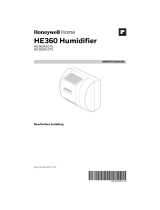
Fig. 1. Typical humidifier installation locations.
Fig. 2. HE360 Humidifier location in relation to air conditioning
cooling coils.
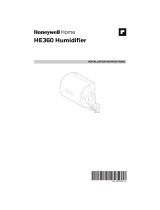
Fig. 3. Humidifier components.
Fig. 4. Position securing clips.
7. Position the humidifier housing in the hole (be sure it is
level), so the locking tabs are in place on the upper and
lower sheet metal edge of the hole.
8. Push in securing clips until completely seated.
9. Drill holes and install the three sheet metal screws at the
top of the humidifier housing. Secure the housing with the
three remaining screws.
10. Reinstall the humidifier pad assembly in the humidifier
housing.
IMPORTANT
For proper operation, be sure the mark on the end of the
humidifier pad is facing up. Check that the water feed
tube is placed in the guide slots of the humidifier housing.
11. Hook the top of the cover to the housing and secure with the
thumbscrew located at the bottom of the cover.
M12808C
HORIZONTAL
DOWN
FLO
LOWBOY
RETURN
RETURN
RETURN
HIGHBOY
RETURN
M12812C
M31023A
COVER
ASSEMBLY
HUMIDIFIER
PAD ASSEMBLY
FEED TUBE NOZZLE
WATER
DISTRIBUTION TRAY
HUMIDIFIER
HOUSING
THUMB
SCREW
M12813B
CLIP CLIP
TOP VIEW – HUMIDIFIER HOUSING
Template (entire sheet) Top of Humidifier
Template (entire sheet)
© 2022 Resideo Technologies, Inc. All rights reserved.
The Honeywell Home trademark is used under license from Honeywell International, Inc. This product is manufactured by Resideo Technologies, Inc. and its affiliates.
www.resideo.com
Resideo Technologies, Inc.
1985 Douglas Drive North, Golden Valley, MN 55422
1-800-468-1502
33-00511—03 M.S. Rev. 06-22 | Printed in United States
WIRING
WARNING
Voltage Hazard.
Moving parts can cause electrical shock and injury.
Disconnect power supply before installation or
servicing.
This device contains a moving fan blade; do not operate
the humidifier without the cover securely attached.
All wiring must comply with applicable local codes,
ordinances and regulations.
For H6062 humidistat, use figures 5 or 6 and
follow the notes below. For mechanical
humidistat, use figures 5, 6, or 8 and follow the
notes below.
IMPORTANT
Select models of fan centers include humidifer taps so the
current sensing relay or sail switch is not needed.
If not using a current sensing relay or sail switch, the
120V humidifier plug must be energized during blower
motor cycles for proper operation.
Red wire connections on humidifier are used for the
H6062 digital humidity controller but are not used for
mechanical humidistats or IAQ thermostats.
For additional mounting and wiring information, refer to the
humidistat installation instructions.
Fig. 5. Typical wiring diagram of sail switch with humidifier.
Fig. 6. Typical wiring diagram of current sensing relay with
humidifier.
Fig. 7. Typical wiring diagram for humidifier using TH8321R
RedLINK VisionPRO or Prestige with EIM.
Fig. 8. Typical wiring diagram for humidifier using fan control
to cycle blower motor fan and humidifier simultaneously.
CHECKOUT
1. Set the thermostat setpoint 10°F (6°C) above the room
temperature.
2. Set the humidity control to a high humidity setting, or place
the setting in the test position.
3. Observe the water running out of the drain line to be sure
the humidifier is working correctly.
4. Check for leaks.
5. Reset the thermostat to a comfortable setting or the
Automatic Humidity Control to the desired frost factor
setting.
NOTE: The furnace blower must be on for the humidifier to
operate.
M39015
1
24V WIRING
RED WIRES NOT USED WITH A MECHANICAL HUMIDISTAT.
2
1
2
C
R
U
U
S
S
24 VAC (CONSTANT)
OUTDOOR SENSOR
YELLOW
WIRES RED WIRES
H6062
HE365
SAIL SWITCH
M39016
1
24V WIRING
RED WIRES NOT USED WITH A MECHANICAL HUMIDISTAT.
2
1
2
C
R
U
U
S
S
24 VAC (CONSTANT)
OUTDOOR SENSOR
YELLOW
WIRES RED WIRES
H6062
HE365
CURRENT
SENSING
RELAY
BLOWER
MOTOR
C
LOW
HIGH
YELLOW
U1
THE HUMIDIFIER CAN BE WIRED TO THE U1, U2, OR U3 TERMINALS ON EIM.
THE THERMOSTAT ISU SETTINGS HAVE DIFFERENT OPTIONS FOR
HUMIDIFIER CONTROL, WINDOW PROTECTION, ETC.
M39017
1
Equipment Interface Module
U1
2
1
2
HUMIDIFIER
MECHANICAL
HUMIDISTAT
120 VAC
TO BLOWER
MOTOR
IGNITION BOX
M12686B
YELLOW WIRES
1
1
2
2
POWER SUPPLY. PROVIDE DISCONNECT MEANS AND
OVERLOAD PROTECTION AS REQUIRED.
24V WIRING.
  • Page 1 1
  • Page 2 2

Honeywell Home HE365 User manual

Type
User manual

Honeywell Home HE365 is a powered flow-through humidifier that works with your warm air furnace blower to provide whole-house humidification. It is compatible with virtually any Honeywell Home humidity control and can be installed in various locations, including the furnace jacket or plenum. The HE365 features a water distribution tray and humidifier pad assembly for efficient moisture distribution. It also includes securing clips for easy installation and a drain line to prevent water damage.

Ask a question and I''ll find the answer in the document

Finding information in a document is now easier with AI