Page is loading ...

Installation Manual for VMAC
System V910017
2016+ Ford F-650 – F-750 Super Duty
(Hydraulic Brakes Only)
6.7 L Power Stroke Diesel


\VMAC – Vehicle Mounted Air Compressors
Toll Free: 1-888-241-2289
Fax: 1-250-740-3201
1
Installation Manual for VMAC
System V910017
2016+ Ford F-650 – F-750 Super Duty
(Hydraulic Brakes Only)
6.7L Power Stroke Diesel
Safety ................................................................................................. 3
Warranty ............................................................................................. 4
General Information .......................................................................... 5
System Identification, Warranty and Warnings .............................. 6
Preparing for Installation .................................................................. 8
Modifying the coolant hoses ............................................................ 12
Modifying Fan Stator ........................................................................ 14
Installing the Separator Tank (AOST), Brackets and Hoses ......... 18
Installing the Cooler .......................................................................... 21
Installing the Tensioner, Compressor and P-clip Brackets .......... 23
Installing the CAC Brackets ............................................................. 28
Routing and Connecting the Hoses ................................................ 31
Installing the VMAC Belt and Fan .................................................... 37
Adding Oil to the System ................................................................. 39
Installing the Control Components ................................................. 40
Connecting the CAC Hoses ............................................................. 44
Completing and Testing the Installation ......................................... 46
Setup, Performance Testing and Adjustments .............................. 48
Air Receiver Tank .............................................................................. 50
Accessory Products ......................................................................... 51
Warranty Registration ....................................................................... 52

VMAC – Vehicle Mounted Air Compressors
Toll Free: 1-888-241-2289
Fax: 1-250-740-3201
2
Document: 1930291
Changes and Revisions
Additional Application Information
• 2016+ Ford F-650 – F-750 Super Duty (Hydraulic Brakes Only) 6.7L
Power Stroke Diesel
Registered Trademarks
All trademarks mentioned in this manual are the property of their respective
owners. Their use by VMAC is for identification of the manufacturers’
products only and does not imply any affiliation to, or endorsement of said
companies.
Loctite®, Loctite® 242 and are registered trademarks of Henkel AG &
Company KGaA.
Ford® and Power Stroke® are registered trademarks of Ford Motor
Company
Important Information
The information in this manual is intended for certified VMAC installers who
have been trained in installation procedures and for people with mechanical
trade certification who have the tools and equipment to properly and safely
perform the installation. Do not attempt this installation if you do not have the
appropriate mechanical training, knowledge and experience.
Follow all safety precautions for mechanical work. Any grinding, bending or
restructuring operations for correct fit in modified vehicles must follow
standard shop practices.
Notice
Copyright © 2017 VMAC Global Technology Inc. All Rights Reserved. These
materials are provided by VMAC for informational purposes only, without
representation or warranty of any kind, and VMAC shall not be liable for
errors or omissions with respect to the materials. The only warranties for
VMAC products and services are those set forth in the express warranty
statements accompanying such products and services, if any, and nothing
herein shall be construed as constituting an additional warranty. You may
print or copy for your personal use any whole page or pages in this
document. All other use, copying or reproduction in both print and electronic
form of any part of this document without the written consent of VMAC is
prohibited. The information contained herein may be changed without prior
notice. Printed in Canada
Revision
Revision Details
Revised
by
Checked by
Implemented
Eng.
Tech.
Qual.
Mech.
Elec.
A
Initial Release
MSP
DSA
AJH
GB
AMG
23 JAN 2017
B
ECN 17-059 Update CAC reducer size
MSP
KRM
N/A
GB
AMG
6 April 2017

\VMAC – Vehicle Mounted Air Compressors
Toll Free: 1-888-241-2289
Fax: 1-250-740-3201
3
Safety
Important Safety Notice
The information contained in this manual is based on sound engineering
principles, research, extensive field experience and technical information.
Information is constantly changing with the addition of new models,
assemblies and service techniques. If a discrepancy is noted in this manual,
contact VMAC prior to initiating or proceeding with installation, service or
repair. Current information may clarify the issue. Any person with knowledge
of such discrepancies who performs service and repair assumes all risks.
Only proven service procedures are recommended. Anyone who departs
from the specific instructions provided in this manual must first assure that
their safety and that of others is not being compromised and that there will
be no adverse effects on performance or the operational safety of the
equipment.
VMAC will not be held responsible for any liability, consequential damages,
injuries, loss or damage to individuals or to equipment as a result of the
failure of any person to properly adhere to the procedures set out in this
manual or standard safety practices. Safety should be your first
consideration in performing service operations. If you have any questions
concerning the procedures in this manual or require any more information on
details that are not included in this manual, please contact VMAC before
beginning repairs.
Safety Messages
This manual contains various warnings, cautions and notices that must be
observed to reduce the risk of personal injury during installation, service or
repair and the possibility that improper installation, service or repair may
damage the equipment or render it unsafe.
This symbol is used to call your attention to instructions concerning
your personal safety. Watch for this symbol; it points out important
safety precautions, it means, “Attention, become alert! Your
personal safety is involved”. Read the message that follows and be
alert to the possibility of personal injury or death. Be alert; your
safety is involved. As it is impossible to warn about every
conceivable hazard, let good common sense be your guide.
This symbol is used to call your attention to instructions on a specific
procedure that if not followed may damage or reduce the useful life
of the compressor or other equipment.
This symbol is used to call your attention to additional instructions or
special emphasis on a specific procedure.

VMAC – Vehicle Mounted Air Compressors
Toll Free: 1-888-241-2289
Fax: 1-250-740-3201
4
Warranty
Standard Product Warranty
For complete warranty information, including both our standard Product
Warranty and Limited Lifetime Warranty requirements, please refer to our
current published warranty located at:
www.vmacair.com/warranty
If you do not have access to a computer, please contact us and we will be
happy to send you our warranty.
VMAC’s warranty is subject to change without notice.
Limited Lifetime Warranty
Effective 1 October 2015 - The Compressor Assembly (excluding Inlet and
Clutch, where applicable) is warranted against manufacturer defects in
materials and workmanship for the lifetime of the Compressor
Assembly. Restrictions apply – refer to VMAC Warranty Policy and VMAC
Limited Lifetime Warranty for full details.
Warranty Registration
The VMAC warranty form is located at the back of this manual. This warranty
form must be completed and sent to VMAC at the time of installation for any
subsequent warranty claim to be considered valid.
There are 4 ways warranty forms can be submitted to VMAC:
Online
www.vmacair.com/warranty/
Email
Fax
(250) 740-3201
Mail
VMAC - Vehicle Mounted Air Compressors
1333 Kipp Road, Nanaimo, BC, Canada V9X 1R3

\VMAC – Vehicle Mounted Air Compressors
Toll Free: 1-888-241-2289
Fax: 1-250-740-3201
5
General Information
Before You Start
Read this manual before attempting installation so that you can familiarize
yourself with the components and how they fit on the vehicle. Identify
variations for different engine models and different situations that are listed in
the manual. Open the package, unpack the components and identify them.
Torque Specifications
All fasteners must be torqued to specifications. Use manufacturers’ torque
values for OEM fasteners. Apply Loctite 242 (blue) or equivalent on all
engine-mounted fasteners. Torque values are with Loctite applied unless
otherwise specified.
STANDARD GRADE 8 NATIONAL COARSE THREAD
Size
1/4
5/16
3/8
7/16
1/2
9/16
5/8
3/4
Foot-pounds (ft•lb)
9
18
35
55
80
110
170
280
Newton meter (N•m)
12
24
47
74
108
149
230
379
STANDARD GRADE 8 NATIONAL FINE THREAD
Size
3/8
7/16
1/2
5/8
3/4
Foot-pounds (ft•lb)
40
60
90
180
320
Newton meter (N•m)
54
81
122
244
434
METRIC CLASS 10.9
Size
M6
M8
M10
M12
M14
M16
Foot-pounds (ft-lb)
4.5
19
41
69
104
174
Newton meter (N•m)
6
25
55
93
141
236
Table 1 – Torque Table
Special Tools Required
• Pneumatic fan wrench removal set (such as Lisle® 43300) or a manual
fan pulley holder (such as KD Tool® KD3900)
Hose Information
Depending on other installed equipment, it might be necessary to move the
air/oil separation tank from its intended location. The hoses used in VMAC
compressor systems have a specific inner liner that is compatible with VMAC
compressor oil. Use of hoses other than those supplied or recommended by
VMAC may cause compressor damage and may void your warranty. Please
contact VMAC for replacement hoses and further information.
Ordering Parts
To order parts, contact your VMAC dealer. Your dealer will ask for the VMAC
serial number, part number, description and quantity. To locate your nearest
dealer, call 1-877-912-6605 or online at www.vmacair.com.

VMAC – Vehicle Mounted Air Compressors
Toll Free: 1-888-241-2289
Fax: 1-250-740-3201
6
System Identification, Warranty and
Warnings
Preparation for installation is very important. Missing a step or an item can
cause problems in the installation or damage to components.
Check off each item as it is completed so that no steps are missed.
Check through the illustrated parts list to ensure that all components are
present and that they are in the correct quantity. If any components are
missing, have the system ID ready and call VMAC technical support at
(888) 241-2289.
Complete the warranty form. The VMAC warranty form is located at the
back of this manual, as well as online at:
http://vmacair.com/warranty/
This warranty form must be completed and returned to VMAC at the time of
installation for any subsequent warranty claim to be considered valid.
The System Identification Number Plate must be attached to
the vehicle at the time of installation. This plate provides
information that allows VMAC to assist with parts and repairs.
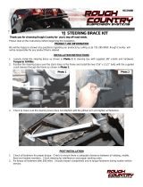
Mark and drill (2x) 7/64 in holes in the top of the cross member in front of
the hood support. Secure the plate with the supplied self- tapping
screws. (Figure 1)
Figure 1 - System Identification Plate
Clean the cross member beside the System ID plate and affix the belt
routing diagram to the cross member.

\VMAC – Vehicle Mounted Air Compressors
Toll Free: 1-888-241-2289
Fax: 1-250-740-3201
7
As part of the installation process, ensure that the operating instruction
label is affixed in an obvious location so that it can be seen by vehicle
operators. A good spot for this is usually on the inside of the door or on
the panel underneath the steering wheel (Figure 2).
Figure 2 - Operating Instruction Label
To alert any technicians that may service the vehicle, affix the warning
label in the engine compartment near the hood latch in a visible location.
Thoroughly clean the selected area before affixing the label (Figure 3).
Figure 3 - Warning Label

VMAC – Vehicle Mounted Air Compressors
Toll Free: 1-888-241-2289
Fax: 1-250-740-3201
8
Preparing for Installation
Do not use a test light to probe for power on vehicle circuits,
the increased current draw of the test light may damage
components.
Ensure that the VMAC Warranty Registration has been filled
out. Install the System Identification Number Plate and
operating instruction label. (Please see page 6 for details).
Locate the blunt-cut OEM SEIC wire harness, on the driver side just
below the OBDII port. Within this bundle, locate the transmission park
signal wire (CET22 grey wire with brown stripe). If CET22 is not present,
locate the neutral signal wire (CET21 green wire with white stripe).
Use a multi meter to verify the transmission park (or neutral) signal. Turn
the key to the “IGN2” position, (do not start the truck), to supply power to
the dash display. The resistance to ground should read close to 0 Ω in
“PARK” (or “NUETRAL” if CET21 is used) and open circuit in all other
gears. Put the vehicle in “PARK” and turn the key to the “OFF” position.
The transmission park signal needs to be electrically verified
with a multimeter to ensure the correct wire is read.
Mark the transmission park (or neutral) signal wire for connection later in
the “Installing the Control Components” section.
Disconnect both batteries to prevent electrical shorts.
Optional: Remove the hood to provide better access to the engine bay.
Drain the primary and secondary radiators into separate, clean
containers. Set the coolant aside for use later.
Disconnect the MAF sensor plug on the air box lid.
Remove the air box.
Cover the air intake port to prevent debris from entering the engine.
Disconnect the hot air intake at the top of the Charge Air Cooler (CAC)
and plug the tube to prevent debris from entering the engine. Retain the
hose clamps.
Disconnect the cold air discharge at the bottom of the CAC and at the
engine intake. Retain the OEM gear clamps
Cover the intake to prevent debris from entering the engine.
Remove the CAC. Retain the grommet, it will be reused later.
Remove the CAC brackets.

\VMAC – Vehicle Mounted Air Compressors
Toll Free: 1-888-241-2289
Fax: 1-250-740-3201
9
Cut the CAC bracket studs flush with the bracket to provide adequate
clearance for the cobra head (Figure 4)
Figure 4 – Remove CAC bracket stud
Remove the lower radiator hose. This will be modified in a later section.
Remove the left and right radiator braces (Figure 5).
Figure 5 – Left and right radiator braces
Cut studs flush
with bracket

VMAC – Vehicle Mounted Air Compressors
Toll Free: 1-888-241-2289
Fax: 1-250-740-3201
10
Remove the hood support cable from the hood.
Remove the left and right radiator brackets (Figure 6).
Figure 6 - Remove the top radiator bracket
Remove the upper radiator hose from the radiator and disconnect the
overflow tube.
Remove the upper radiator shroud. The A/C lines may need to be
deflected slightly to clear the indent in the shroud (Figure 7).
Figure 7 – Outer radiator shroud
Remove the lower fan shroud by compressing the fan stator gasket and
pull the lower shroud up. The A/C lines may need to be deflected slightly
to raise the shroud past them.
Place cardboard between the radiator and the fan.
Remove the fasteners from the fan stator (Figure 7).
Disconnect the fan harness.
Remove bracket
Remove the upper
radiator shroud
Remove the
fasteners from
the fan stator

\VMAC – Vehicle Mounted Air Compressors
Toll Free: 1-888-241-2289
Fax: 1-250-740-3201
11
Remove the fan using a pneumatic fan wrench (such as Lisle 43300).
Remove the fan and the stator from the engine bay as one unit.
Installing the VMAC crank pulley
Remove the 4 OEM crank pulley balancer bolts and discard them. Install
the VMAC crank pulley on the OEM balancer/pulley. Ensure the center
locating boss goes into the OEM balancer.
Apply Loctite 242 (blue) to the 4 supplied M12 x 60 mm crank pulley
bolts, add the supplied M12 washers and install the VMAC crank pulley.
Torque the crank pulley bolts to 22 ft•lbs.
Tighten the crank pulley bolts an additional 90°.

VMAC – Vehicle Mounted Air Compressors
Toll Free: 1-888-241-2289
Fax: 1-250-740-3201
12
Modifying the coolant hoses
□ Remove the lower primary coolant hose that is attached to the primary
cooler and engine (Figure 8).
Figure 8 – Modifying the lower radiator hose
□ Measure and cut the OEM radiator hose 11 in from the edge shown
(Figure 9).
Figure 9 – Modifying the lower radiator hose
From radiator
To engine
From radiator
11 in

\VMAC – Vehicle Mounted Air Compressors
Toll Free: 1-888-241-2289
Fax: 1-250-740-3201
13
□ Measure 9 in along the outside edge of the OEM cuff. Mark and cut the
hose (Figure 10).
Figure 10 – Modifying the lower radiator hose
□ Discard the 90° rubber section cut off from the OEM radiator hose
(Figure 11).
Figure 11 – Modifying the lower radiator hose
From radiator
From radiator (discard)
To engine
Modified OEM
radiator hose
9 in

VMAC – Vehicle Mounted Air Compressors
Toll Free: 1-888-241-2289
Fax: 1-250-740-3201
14
Modifying Fan Stator
□ Lay the fan stator on a work surface with the rubber gasket side down.
The mounting legs that are closest together are the bottom mounts.
(Figure 12).
Figure 12 – Fully modified fan stator
FEAD belt relief (top left of stator) (Figure 13, Figure 14)
Measure 12 1/2 in from the OEM split in the gasket (cut line “A”) on the
left, outside edge of the stator and mark a cut line (Figure 13).
Install a new rivet on the gasket side of the marked cut line to replace
the rivet lost in the modification.
Measure 10 in from the OEM split on the left, inside edge of the stator
and mark a cut line (Figure 13). The line drawn between these 2 points
is cut line “B”.
Figure 13 – FEAD belt relief (top left)
12 1/2 in
10 in
Top of stator
OEM split
Crank pulley relief
FEAD belt relief
OEM split
OEM split

\VMAC – Vehicle Mounted Air Compressors
Toll Free: 1-888-241-2289
Fax: 1-250-740-3201
15
At the OEM split, mark the cut line “A” 1/2 in deep (measured from the
vane surface) (Figure 13 and Figure 14).
At cut line “B”, mark the cut line 3/4 in deep (measured from the vane
surface) (Figure 13and Figure 14).
Figure 14 – Top left stator modification
□ Using a grinder or similar tool, remove the 3 vanes below the OEM split
(Figure 15).
Figure 15 – Remove stator vanes
Crank pulley relief (bottom of stator) (Figure 16, Figure 17,
Figure 18, Figure 19)
Measure 6 1/4 in from both sides of the centreline. Mark the left-hand
outside edge as “C”, mark the right hand outside edge as “D” (Figure
16).
Mark a cut line 3/4 in from, and parallel to, the outside edge of the left
hand bottom mount as cut line “E”.
Mark a cut line 3/4 in from, and parallel to, the outside edge of the right
hand bottom mount as cut line “F”.
Mark a cut line from “C” (following the curvature of the stator) to the
bottom of the cut line of the left hand bottom mount as cut line “G”.
Mark a cut line from “D” (through the middle of the radius of the vane) to
the bottom of the cut line of the right hand bottom mount as cut line “H”.
Mark horizontal cut lines from the inside of the left hand mount and the
inside of the right hand mount, just underneath the 90° turn, as cut line
“J” and “K”.
Remove
1/2 in
Top
Bottom
A
B

VMAC – Vehicle Mounted Air Compressors
Toll Free: 1-888-241-2289
Fax: 1-250-740-3201
16
Mark a cutline between “G” and “H”, 3/4 in from the top surface of the
stator as cut line “L”.
Figure 16 – Fan stator crank pulley relief
The crank pulley relief requires removing a portion of the
stator’s mount supports. Remove as little material as possible
to provide clearance for the crank pulley while maintaining the
structure of the stator mount.
□ See the figures below for more detail indicating the cut lines for the lower
portion of the stator (Figure 17, Figure 18, Figure 19).
Figure 17 – Bottom left mount
Figure 18 – Bottom right mount
Figure 19 – Inside view
6 1/4 in
10 in
℄
C
E
G
J
L
6 1/4 in
D
F
H
K

\VMAC – Vehicle Mounted Air Compressors
Toll Free: 1-888-241-2289
Fax: 1-250-740-3201
17
□ Optional: Make a horizontal notch on the inside of the bottom mounts to
assist with remounting the stator on the engine (Figure 20, Figure 21).
Figure 20 – Bottom left mount
Figure 21 – Bottom right mount
Drill out the OEM rivets as required.
Make the serpentine belt and crank pulley relief cuts
(Figure 22, Figure 23).
Figure 22 – Crank pulley relief
Figure 23 – FEAD belt relief

VMAC – Vehicle Mounted Air Compressors
Toll Free: 1-888-241-2289
Fax: 1-250-740-3201
18
Installing the Separator Tank (AOST),
Brackets and Hoses
Apply Loctite 242 (blue) to all fasteners.
Installing the Air Oil Separator Tank
The Air Oil Separator Tank (AOST) will be mounted roughly centered on the
first cross member behind the cab.
□ Carefully remove the brake lines from the 2 guides. Unbolt the OEM line
guides and set aside for later use (Figure 24).
Figure 24 – Line guides
□ Install the OEM line guides onto the AOST mount brackets using the
supplied flat head bolts (Figure 25).
Figure 25 – AOST brackets
Line guide
fasteners
Lines guides
/