Page is loading ...

1135DB Wireless Siren
Description
The Model 1135DB Wireless Siren provides 110 decibels of annunciation and comes
with a wall, cover tamper, survey LED, and two batteries. Multiple sirens can be
activated simultaneously by the panel via the Trip with Panel Bell feature.
Compatibility
All DMP 1100 Series Wireless Receivers and Panels
What is included
The 1135DB includes the following:
• One1135DBWirelessSiren
• Two3.0VLithiumCR123Abatteries
• Hardwarepack
• Serialnumberlabel
• Double-sidedtape
Serial Number
Foryourconvenience,twoadditionalpre-printedserialnumberlabelsareincludedforthesirenoutput.Priortoinstalling
thewirelesssiren,recordtheserialnumberorplacethepre-printedserialnumberlabelonthepanelprogrammingsheet.
This number is required during programming.
Programming the 1135DB Siren Output in the Panel
Refertotheappropriatepanelprogrammingguideasneeded.InOutputInformation,enteranoutputnumber,output
name,eight-digitserialnumber,supervisiontime,andsettheTripwithPanelBelloptiontoYES.
Trip with Panel Bell Option
SelectYEStohavethe1135DBWirelessSirenfollowthepanelbelloutput
includingbellcutofftime.TheON/OFFstateofthesirencannotbechanged
viatheoutputmenuoranyotherpanelfunction.DefaultisYES.
Note: When the panel is reset, or programming is complete, the supervision
time is reset. If the panel has been powered down for more than one hour,
the1135DBmaytakeuptoanadditionalhourtosendasupervisionmessage
unless tripped, tampered, or powered up. This operation extends battery life.
Amissingmessagemaydisplayonthekeypaduntilthesupervisionmessageis
sent. In addition, if the siren is on when the panel is powered down, the siren
automatically turns off after 15 minutes.
Installing the Wireless Siren
Selecting a Location
The1135DBprovidesasurveycapabilitytoallowonepersontoconrm
communication with the receiver while the cover is removed. The 1135DB
PCBRedSurveyLED(SeeFigure2)turnsonbrightlywheneverdataissentto
thereceiverthenimmediatelyturnsoffwhenthereceiveracknowledgement
is received. Pressing the tamper switch is a convenient way to send data to
thereceivertoconrmoperation.Whenthe1135DBdoesnotreceivean
acknowledgementfromthereceiverthesurveyLEDremainsonforabout8secondstoletyouknowcommunicationis
notestablished.CommunicationisalsofaultywhentheLEDashesbrightlymultipletimesinquicksuccession.Relocate
the 1135DB or receiver until the LED immediately turns off when tampered indicating the 1135DB and receiver are
communicatingproperly.Propercommunicationbetweenthe1135DBandreceiverisveriedwhenforeachpressor
releaseofthetamperswitch,theLEDblinksimmediatelyonandimmediatelyoff.
Tamper Switches
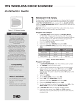
The 1135DB is equipped with a case tamper and a wall tamper. A two position header is
provided to disable the wall tamper. To disable the wall tamper, place the jumper across
the two pins of the header. If wall tamper is required, place the jumper over just one
pin for storage.
Note:Ifmountingusingthesupplieddouble-sidedtape,thewalltampermustbe
disabled.
Mounting the Siren
1.Removethelockingscrewsfromthetopandbottomofthesirenhousing.Liftthe
cover from the bottom to remove.
2.Mountthe1135DBonaatwallensuringthatthewalltamperswitchmakesproper
contact with the wall. Use the supplied screws in the mounting hole locations as
showninFigure2,orusethesupplieddouble-sidedtape.Mountthesirenaway
from metal objects. Do not install the 1135DB within 4 feet of the panel as the RF
gain of the transmitter may inhibit proper communication.
3.Setthecoverbackintoplaceandreplacethelockingscrews.
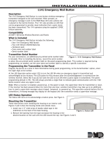
Figure 1: 1135DB Wireless Siren
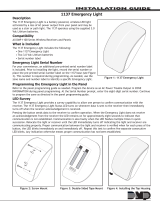
Figure 2: Survey LED and Mounting Holes
Mounting Holes
Model
1135
RED LED
(SURVEY)
TAMPER
SWITCH
SOUNDER
Mounting Holes
Red
Survey
LED
Locking Screw
Locking Screw
WALL
TAMPR DIS
Coil
Board
Tamper
Disable
Figure 3: Wall Tamper
Wall
Tamper
INSTALLATION GUIDE

LT-1224 © 2015 Digital Monitoring Products, Inc.
15155
800-641-4282
INTRUSION • FIRE • ACCESS • NETWORKS
www.dmp.com 2500 North Partnership Boulevard
Designed, Engineered and
Assembled in U.S.A.
Springeld, Missouri 65803-8877
Powering the 1135DB
Note:Whensettingupawirelesssystem,itisrecommendedtoprogramthesiren'soutputnumberinthepaneland
connect the receiver before installing batteries in the 1135DB.
Battery Power
Observepolaritywheninstallingthebatteries.Useonly3.0VLithiumbatteries,DMPModelCR123,ortheequivalent
battery from a local retail outlet.
1.Removethelockingscrewfromthesideofthesirenhousing.
2.Liftthecoverfromthebottomtoremove.
3. If replacing the batteries, remove the old batteries and dispose of properly. Always replace both batteries at the
same time.
Caution:Properlydisposeofusedbatteries.Donotrecharge,disassemble,heatabove212°F(100°C),orincinerate.
Thereisariskofre,explosion,andburnswithimproperdisposal.
4.PlacethetwoCR123batteriesintheholdersandpressintoplace.SeeFigure2forbatterylocation.
5.Setthecoverbackintoplaceandreplacethelockingscrew.
Battery Life Expectancy
Batterylifeexpectancyforthe1135DBis3yearswherethesirenisoperatedforveminutesonceamonth.Refertothe
panelprogrammingguideasneeded.DMPwirelessequipmentusestwo-waycommunicationtoextendbatterylife.
The following situation can extend battery life expectancy:
• Infrequentsirenon/offoperations
• Extendtransmittersupervisiontimeinpanelprogramming
The following situations can reduce battery life expectancy:
• Multiplesirenon/offoperations
• Wheninstalledinextremehotorcoldenvironments
FCC Information
ThisdevicecomplieswithPart15oftheFCCRules.Operationissubjecttothefollowingtwoconditions:
(1)Thisdevicemaynotcauseharmfulinterference,and
(2)thisdevicemustacceptanyinterferencereceived,includinginterferencethatmaycauseundesiredoperation.
Theantennausedforthistransmittermustbeinstalledtoprovideaseparationdistanceofatleast20cm(7.874in.)fromall
persons. It must not be located or operated in conjunction with any other antenna or transmitter.
Changesormodicationsmadebytheuserandnotexpresslyapprovedbythepartyresponsibleforcompliancecouldvoidthe
user’s authority to operate the equipment.
Note: ThisequipmenthasbeentestedandfoundtocomplywiththelimitsforaClassBdigitaldevice,pursuanttopart15of
theFCCRules.Theselimitsaredesignedtoprovidereasonableprotectionagainstharmfulinterferenceinaresidential
installation. This equipment generates, uses and can radiate radio frequency energy and, if not installed and used
inaccordancewiththeinstructions,maycauseharmfulinterferencetoradiocommunications.However,thereisno
guarantee that interference will not occur in a particular installation. If this equipment does cause harmful interference
to radio or television reception, which can be determined by turning the equipment off and on, the user is encouraged
to try to correct the interference by one or more of the following measures:
- Reorientorrelocatethereceivingantenna.
- Increasetheseparationbetweentheequipmentandreceiver.
- Connecttheequipmentintoanoutletonacircuitdifferentfromthattowhichthereceiverisconnected.
- Consultthedealeroranexperiencedradio/TVtechnicianforhelp.
Specications
Battery
LifeExpectancy 3Years
Type 3.0VLithiumCR123A
See Battery Life Expectancy for full details.
FrequencyRange 903-927MHz
Decibel Level 110 dB at 3 ft.
Dimensions 4.5”Lx4.5”Wx1.25”H
Color White
HousingMaterial FlameretardantABS
Accessories
CR123 3.0VLithiumBattery
Compatibility
XTL Series Panels
XT30/XT50SeriesPanels(usingsoftwareversion106orhigher)
XR100/XR500SeriesPanels(usingsoftwareversion207or
higher)
XR150/XR350/XR550SeriesPanels
AllDMP1100SeriesWirelessReceiversVersion200orhigher
Patents
U.S.PatentNo.7,239,236
Certications
FCCPart15RegistrationIDCCKPC0123
ICRegistrationID5251A-PC0123
/