DETECTOR WITH DIGITAL FREQUENCY CONVERSION
INSTALLATION GUIDE
ABT DUAL-BEAM ACTIVE PHOTOELECTRIC INTRUDER

ABT-20 (Outdoor 20m, Indoor 60m)
ABT-30 (Outdoor 30m, Indoor 90m)
ABT-40 (Outdoor 40m, Indoor 120m)
ABT-60 (Outdoor 60m, Indoor 180m)
ABT-80 (Outdoor 80m, Indoor 240m)
ABT-100 (Outdoor 100m, Indoor 300m)
Model:
Wiring terminal
Tamper switch
Indicator
Vertical fine-tune knob
Lens
Voltage test hole
Response time
Adjustment knob
Receiving box
Housing locking screw
Viewfinder
Bracket
Collimation hole
LEVEL: Lightness of the indicator increases with
the accuracy of beam alignment.
ALARM: The indicator turns on when alarm
presents.
GOOD: The green indicator turns on when the
beam aligns with the receiver. If fails to align, the
indicator will off.
POWER: Transmitting indicator

Direct sunlight, lamplig
Installation heigh 0.7m 1.0m
Beam spread diameter
Guarding distance
50mm
50mm
Multi sensors may be used for long-distance
guarding. Please install according to the below
diagram to avoid interference between beams.
Adjustable angle: horizontal 90
vertical 10
Horizontal 180 ( 90 )
V
S
ABT-20
ABT-30
ABT-40
ABT-60
ABT-80
ABT-100
G
B
20m
30m
40m
60m
80m
100m
0.6m
0.7m
1.0m
1.5m
1.8m
2.1m

15mm
1.Remove the cover
2.Attach the paper stencil onto the location
where the equipment is to be mounted, and
drill the holes in the positions on its mark.
3.Put the cable through the hole for wiring.
4.Fix the main body onto the wall
5.Connect the cable to the wire terminal.
6.Put on the cover after adjusting
the response time of the beam.
Installation of fixed bracket
1.Drill a hole on the bracket and
extend out the cable from it.
2.Remove the cover.
3.Fasten the base-plate to the bracket.
(Back-to-back installation guiding diagram)
Wiring hole
Tamperproof
switch terminal
Tamperproof
switch terminal
spare terminals
power supply
power supply
transmitter
alarm output
receiver
Wiring distance between transmitter and receiver
DC13.8V
300m
400m
700m
1000m
DC24V
300m
800m
1400m
2000m

1.Remove the cover and connect power.
2.Observe the collimation effect at a distance of 5cm
from the viewfinder.
3.Adjust the vertical adjustment screw and the
horizontal angle adjusting wheel in order that the
image of opposite detector falls into the central part
of the viewing hole. At this time, the GOOD indicator
of receiver shall light up; if not, adjust it repeatedly.
The accuracy of beam alignment turns higher;
the red LEVEL indicator becomes brighter.
5cm
Vertical adjustment screw
down
up
horizontal adjustment bracke
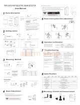
1. Insert the test pen into the test hole (please
note the +,- polarity)
2. First adjust the horizontal angle until the test
hole voltage output maximize. Then adjust the
vertical angle by the same way till the voltage
reaches the value above that of below diagram.
3. If it can't reach 1.1V or higher voltage, the
transmitter and receiver shall be regulated again.
Multimeter selects DC 10V

:1 F 2
F (1.2m/s):3 N (0.7m/s):4 S (0.4m/s):5
W
.
The 2 indicators of green LED light up
GOOD LEVEL indicators light up
The red ALARM indicator light up
T
Transmitting
R

The LED of the transmitter doesn't light up
Power open circuit
The LED of the receiver doesn't light up
Power f open circuit
The LED of the receiver doesn't light up
when the
ABT-20
20m
60m
200m
ABT-30
30m
60m
350m
ABT-40
40m
120m
450m
ABT-60
60m
180m
650m
ABT-80
80m
240m
900m
ABT-100
100m
300m
1100m
O
H
V
Alert distance
Calefaction housing (optional)
PC resin
658g(receiver +transmitter)
1150g
2 beams
2 beams blocked simultaneous
Infrared digital pulse beam
50 700msec
Relay contact output: NO. NC contact rating: AC/DC30V 0.5AMax
DC13.8 24V AC11 18V P 15W
-25 -55 5%-95%RH(relative humidity)
Refer to its diagram
Contact output: NC contact rating DC24V 0.5Amax
180 ( 90 )
20 ( 10 )
40mAmax 40mAmax 55mAmax 55mAmax 65mAmax 65mAmax

Recommended
installation
Installation bracket
80 75mm
T
T-100
100 120mm
T-200
200 120mm
I
I-100
100mm
I-200
200mm
Dimensions
The product has got the 3C and CE approval already
and is now applying for the UL approval.
Copyright : Shenzhen Meian Technology Co.,Ltd.
/