Page is loading ...

Photoelectric Beam Detector
SASO
PB100A
Installation Instructions
SASO
-
PB100A
•Features
- Digital CPU for greater stability
- Selectable 4-channel beam frequencies
(SASO-PB100A)
- Lighting & surge protection
- Protection against frost/dew
- Maximum beam arrival distance : 10 times of protection range
- IP 54 (Protection against water and dust)
- Digital CPU and 4-channel
1. Parts Description
Power LED
Terminals
Monitor jack
Good LED Tamper
Vertical
adjustment
screw
View finder
Lens
Alarm LED
Response
time
adjustment Channel
Horizontal
adjustment
2. Cautions on Installation
Cover Transmitter
Receiver Mounting plate
Avoid strong light from sun,
automobile headlights etc.
shining on transmitter or
receiver (avoid light in a
direct path of
±
2
˚
of optical
Do not install the unit on
unsteady surfaces. Do not install in a site where
beam may be interrupted by
trees or plants, consider
seasonal changes.
Do not install in places where
units may be splashed
continuously by dirty water or
direct sea spray. (Causes dirt
or salt built
-
up on enclosures)
direct
path
of
±
2
of
optical
axis
or
salt
built
up
on
enclosures)
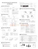
3. Response time
1. Run at full speed
(6.9m/s) - 50 msec. 2. Walk with quick steps
(1.2m/s) - 200msec. 3. Walking (0.7m/s)
- 300msec. 4. Walk with slow steps
(0.5m/s) - 500msec. 5~6. Go over a fence(0.3m/s)
- 700msec.
Response time
adjustment
50msec 700msec

4. Protection distance and Expansion of beam
MODEL LA
SASO-PB30plus 30m 0.9m
SASO-PB60plus 60m 1.8m
SASO-PB30Alpha 30m 0.9m
SASO-PB60Alpha 60m 1.8m
Protection distance and Expansion of Beam
Protection distance L
A
5. Installation
- Remove cover from unit
and slide the mounting
plate to detach it.
- Break grommet on mounting plate
and pull wire through it. Secure
the plate with 4mm screws.
- When exposed wired, break knock-
outs on the rear of unit, pull wire
through as the figure and attach it to
the mounting plate.
- After wiring is completed,
adjust alignment, check
operation and attach cover.
5-1. Wall mount
5-2. Pole mount
Wire hole
6. Optical Alignment
* Unit mounts to a 1.25”(40mm) - 1.80”(46mm)
(external diameter) pole
Read voltage from monitor jack with volt-meter(digital) to confirm optical
alignment and to obtain the highest reliability.
1. Supply power with cover detached.
2. Set Transmitter lens to Receiver lens by the view finder
Look through view finder on either side and line-up optics horizontally and vertically
until the opposite unit is visible. (Using the adjustment, the lens can move
horizontally(±90˚) and vertically(±10˚) allowing the unit to work in all directions )
The opposite Transmitter or Receiver should appear on the view finder of inside
View finder
The
opposite
Transmitter
or
Receiver
should
appear
on
the
view
finder
of
inside
middle mirror.
3. Adjust the Transmitter’s horizontally and vertically to get highest voltage reading.
Adjust the Receiver’s horizontally and vertically to get highest voltage reading.
- Reference table.
Monitor Jack Output Voltage Beam level
2.2V or over Good
180’
20’
4. Confirm the beam level by inserting a tester
in monitor jack of receiver.
2.0V under Readjustment
Receiver

7. Channel setting
This function is used for the purpose of preventing cross-talk or bypass of beams which may occur in
line protection or 2-stacked protection. Set beam channel.
8. Wiring
1ch 2ch 3ch 4ch
TransmitterReceiver
Terminal configuration
VCC : DC10.8~18V
GND
Normal Close
Common
NO
1
2
3
4
NO
5
6
7
8
Terminal configuration
Normal Open
Tamper
Tamper
Spare
12 3 4 5 6 7 8 12 678
Symptom
Operation LED does not
light
Possible Cause
1. No power supply.
2. Bad wiring connection or broken wire,
short
Remedy
1. Turn on the power.
2. Check wiring.
9. Troubleshooting
Alarm LED does not light
when the beam is broken.
Alarm LED continues to
li ht
1. No power supply.
2. Bad wiring connection or broken wire,
short.
3. Beam is reflected on another object
and sent into the receiver.
4. Two beams aren’t broken
simultaneously
1. Beam alignment is out.
2Shdi bj tbt T dR
1. Turn on the power.
2. Check wiring.
3. Remove the reflecting object or
change beam direction.
4. Break 2 beams simultaneously.
1. Check and adjust again.
2R th hdi bj t
li
g
ht
Intermittent alarms.
2
.
Sh
a
di
ng o
bj
ec
t
b
e
t
ween
T
r. an
d
R
e.
3. Optics of units are soiled.
4. Improper channel.
1. Bad wiring connection.
2. Change of supply voltage.
3. Shading object between Tr. and Re.
4. A large electric noise source, such as
power machine, is located nearby Tr.
and Re
2
.
R
emove
th
e s
h
a
di
ng o
bj
ec
t
.
3. Clean the optics with a soft cloth.
4. Check channel.
1. Check again.
2. Stabilize supply voltage.
3. Remove the shading object.
4. Change the place for installation.
and
Re
.
5. Unstable installation of Transmitter
and Receiver.
6. Soiled optics of Tr. and Re.
7. Improper alignment.
8. Small animals may pass through the 2
beams
5. Stabilize.
6. Clean the optics with a soft cloth
7. Check and adjust again.
8.Set the response time longer.

/