Page is loading ...

Photoelectric Beam Detector
SASO-PB30SA / PB80SA / PB80SA / PB100S
A
Installation Instructions
1. Description
We appreciate tour purchase of our photoelectric beam detector. This detector will provide long and dependable service when
properly installed. Please read this instruction manual carefully for correct and effective use.
Please note : This sensor is designed to detect intrusion and to initiate an alarm, it is not a burglar-preventing device. Maker is
not responsible for damage, ,injury or losses caused by accident, theft, natural disasters, abuse, misuse, abnormal usage, faulty
installation or improper maintenance.
Response time
adjustment
Terminals
Good LED
Alarm LED
Lens
Monitor jack
Tamper
Vertical
Wiring Hole
Power LED
2. Cautions on Installation
Vertical
Adjustment screw
View finder
Cover Transmitter
Receiver Plate
Avoid strong light from sun,
auto-mobile head-lights etc.
shining on transmitter or
receiver
Do not install the unit on
unsteady surfaces. Do not install in a site where
beam may be interrupted by
trees or plants, consider
seasonal changes.
Do not install in places where
units may be splashed
continuously by dirty water or
direct sea spray.
3. Installation Hints
①Remove cover from unit
and slide the mounting
plate to detach it.
②Break grommet on mounting
plate and pull wire through it.
Secure the plate with 4mm
screws.
③When exposed wired, break
knock-outs on the rear of unit,
pull wire through as the figure
and attach it to the mounting
plate.
④After wiring is completed,
adjust alignment, check
operation and attach cover.
3-1. Wall mount
3-2. Pole mount (Pole size : Φ38 ~ Φ44mm)
①Remove cover from unit and slide the mounting
plate to detach it.
②Attach pole brackets to pole and secure to mounting
plate with screws
plate
with
screws
.
③Attach sensor body.
④Pull through wire.
⑤Connect terminals.
⑥After wiring is completed, adjust alignment, check
operation and attach cover.

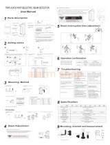
1. Run at full speed
(6.9m/s) - 50msec. 2. Walk with quick steps
(1.2m/s) - 200msec. 3. Walking (0.7m/s)
- 300msec. 4. Walk with slow steps
(0.5m/s) - 500msec. 5~6. Go over a fence(0.3m/s)
- 700msec.
4. Response time
Response time
adjustment
5. Expansion of beam
700ms50ms
MODEL LA
SASO-PB30SA 30m 0.9m
SASO-PB60SA 30m 0.9m
SASO-PB80SA 80m 2.4m
SASO-PB100SA 100m 3.0m
- Protection distance and Expansion of Beam
Protection distance L
A
6. Position of Installation
- Heights of installation
Install the detector at a height of 80~100cm
to catch human pattern.(Pole mount)
- Position of installation
Example 1 Example 2 Example 3
Read voltage from monitor jack with volt
meter(digital) to confirm optical
7. Optical Alignment
80~100cm
Read
voltage
from
monitor
jack
with
volt
-
meter(digital)
to
confirm
optical
alignment and to obtain the highest reliability.
1. Supply power with cover detached.
2. Set Transmitter lens to Receiver lens by the view finder
Look through view finder on either side and line-up optics horizontally and vertically
until the opposite unit is visible. (Using the adjustment, the lens can move
horizontally(±95˚) and vertically(±10˚) allowing the unit to work in all directions )
The opposite Transmitter or Receiver should appear on the view finder of inside
middle mirror.
3. Adjust the Transmitter’s horizontally and vertically to get highest voltage reading.
Adjust the Receiver
’
s horizontally and vertically to get highest voltage reading
Adjust
the
Receiver s
horizontally
and
vertically
to
get
highest
voltage
reading
.
- Reference table.
Very GoodON3.3 ~ 4V
GoodON3.1 ~ 3.3V
Alignment againOFFLess than 3.0V
ConditionR:Green LEDMonitoring
Digital
Multi meter
Vertical
Adjustment :±10˚
4. Confirm the beam level by inserting a tester
in monitor jack of receiver.
Horizontal
Adjustment :±95˚

8. Terminal Arrangement
Wiring distance
①②③④⑤⑥
TransmitterReceiver
①②
DC 12V
AWG 22/Ø 0.65mm/0.65mm2140m
AWG 20/Ø 0.8mm/0.8mm2220m
AWG 18/Ø 1.0mm/1.0mm2345m
AWG 17/Ø 1.1mm/1.2mm2495m
-
Wiring
distance
Voltage
Wiring size DC 24V
1,320m
2,000m
3,150m
4,500m
NO
4
5
6
Usage
VCC
GND
Normal Close
NO
1
2
3
Usage
Normal Open
Common
Tamper
- Connection
Example 1 Example 2 Example 3
Note
1) Maximum wiring distance when two or more sets are connected
is the value above divided by the number of sets.
2) The signal line can be wired to distance of up to 1,000m with
AWG22 telephone line.
(12VDC)
Control Panel
}
P
o
w
er
Control Panel
(12VDC)
(12VDC)
Control Panel
TRRT
}
}
}
1 2 1 2 3 4 1 2 1 2 3 4
Alarm(1ch)
oe
Alarm(2ch)
TRRT
}
}
1 2 1 2 3 4 1 2 1 2 3 4
Alarm Signal
Power
TR
1 2 3 4
1 2
(12VDC)
}
}Alarm Signal
Power
9. Troubleshooting
Problem
Operation LED does not light
Alarm LED does not light
Possible Cause
1. No power supply.
2. Bad wiring connection or broken wire,
short
1. No power supply.
Possible Solution
1. Turn on the power.
2. Check wiring.
1. Turn on the power.
when the beam is broken.
Alarm LED continues to
light
2. Bad wiring connection or broken wire, short.
3. Beam is reflected on another object and sent
into the receiver.
4. Two beams aren’t broken simultaneously
1. Beam alignment is out.
2. Shading object between Tx. and Rx.
3. Optics of units are soiled.
4. Improper channel.
2. Check wiring.
3. Remove the reflecting object or change
beam direction.
4. Break 2 beams simultaneously.
1. Check and adjust again.
2. Remove the shading object.
3. Clean the optics with a soft cloth.
4. Check channel.
Intermittent alarms. 1. Bad wiring connection.
2. Change of supply voltage.
3. Shading object between Tr. and Re.
4. A large electric noise source, such as power
machine, is located nearby Tx. and Rx.
5. Unstable installation of Tx. and Rx.
6. Soiled optics of Tx. and Rx.
7. Improper alignment.
1. Check again.
2. Stabilize supply voltage.
3. Remove the shading object.
4. Change the place for installation.
5. Stabilize.
6. Clean the optics with a soft cloth
7. Check and adjust again.
7.
Improper
alignment.
8. Small animals may pass through the 2 beams
7.
Check
and
adjust
again.
8.Set the response time longer.

10. Specification
SASO-PB60SA SASO-B100SASASO-PB30SA
Double modulation pulsed beams by LED
Infrared beam
Simultaneous breaking of 2 beamsDetection system SASO-PB10SAModel
Outdoor 60m
Indoor 120m
Green LED
(
Sensitivit
y
Good
)
/ Red ON : When an alarm is initiatedReceive
r
Transmitter
Outdoor 100m
Indoor 200m
10.8V ~ 25V DC(Non-polarity)
Outdoor 30m
Indoor 60m
Green LED ON : Power ON
LED
50msec to 700msecResponse time
Supply voltage Less 46mA Less 61mA Less 80mA Less 88mA
Current
Outdoor/Indoor 100m
Max. beam range
Outdoor 10m
Indoor 20m
Protection range
Double
modulation
pulsed
beams
by
LED
Infrared
beam
Outdoor/Indoor 300m Outdoor/Indoor 600m Outdoor/Indoor 1,000m
(y)
Out door / In doorMounting position Horizontal : 190˚ (±95˚), Vertical : 20˚ (±10˚)Beam adjustment -25℃~ 70℃Temperature
Dry contact relay output form N/C(Receiver only)
Contact action : Activated when cover is detached
Contact capacity : 30V(AC/DC) 1A or less
Tamper output
Dry contact relay output form C
Contact action : Interruption time + delay time(2+0.5sec)
Contact capacity : 30V(AC/DC) 1A or less
Alarm output
Rx : 338g, Tx : 324g
Monitor jack output, Anti-frost coverFunction Pole attachment(2pcs./set, pole size : ø38~44mm) / Transmitter tamper switchOption
Weight 73 x 167 x 78mm(WxHxD)External dimensions IP 55IP rating PC resinMaterial
* Caution : Please consult the instruction manual to ensure safe and proper operation of the product.
Specification and design are subject to change without prior notice for improvement.
SASO products are warranted to be free from defects in
Limited Warranty
11. External Dimension
material and workmanship 12 months from original date
of shipment. Our warranty does not cover damage or
failure caused by Acts of God, abuse, misuse, abnormal
usage, faulty installation, improper maintenance or any
repairs other than those provided by SASO. All implied
warranties with respect to SASO, including implied
warranties for merchantability and implied warranties for
fitness, are limited in duration to 12 months from original
78
73
date of shipment. During the warranty period, SASO will
repair or replace, at its sole option, free of charge, any
defective parts returned prepaid. Please provide the model
number of products, original date of shipment and nature
of difficulty being experienced. There will be charges
rendered for product repairs made after our warranty
period has expired.
167
/