Page is loading ...

INSTALLATION GUIDE
Thinline™ LCD Keypads
Models 7060, 7063, 7070, 7073
Aqualite™ LCD Keypads
Models 7060A, 7063A, 7070A, 7073A
Security Command™ LCD Keypads
690/690F, 790/790F, 693/793

LCD Keypad Installation Guide 1
© 2006 Digital Monitoring Products, Inc.
Information furnished by DMP is believed to be accurate and reliable.
This information is subject to change without notice.

LCD Keypad Installation Guide 1
DMP Keypads
The DMP Thinline™, Aqualite™, and Security Command™ LCD Keypads offer
exible features and functionality in stylish design choices.
32-Character Display
Armed LED
Po
wer LED
Data Entry Digit keys
COMMAND Key
Back Arrow Key
Select Keys
1 2 3 4
9 0
CMD
5 6 7 8
ABC PRINTING
F R I 2 : 51 AM
Thinline™/Aqualite™ Keypad
�
Security Command™ Keypad
Each keypad provides four 2-button Panic keys, AC power LED, Armed LED,
32-character display, backlit keyboard with easy-to-read lettering and an
internal speaker. The logo on Thinline and Aqualite keypads is also backlit.
The Models 7070/7070A, 7073/7073A, 790/790F, and 793 keypads provide four
fully programmable Class B, Style A protection zones you can program for a
variety of burglary and access control applications.
The Model 7063/7063A, 7073/7073A, and 693/793 keypads provide a built-in
proximity card reader designed to read HID proximity credentials. The Model
7073/7073A and 793 keypads provide a door strike relay and allow Wiegand
input from HID, DMP, or other external card readers.

2 LCD Keypad Installation Guide
LCD Keypad Installation Guide 3
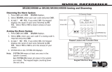
Installing the Keypad
All DMP keypad housings are designed to easily install on any 4” square box,
3-gang switch box, DMP 695 and 696 backbox, or a at surface. Figure 1 shows
the keypad housing base mounting hole locations.
Remove the Cover
The keypad housing is made up of two parts: the front, which contains the
circuit board and keyboard components and the base. Use the following steps
and gures to separate the keypad front and base.
1. Insert a at screwdriver into
one of the slots on the bottom
of the keypad and gently lift the
screwdriver handle toward you
while pulling the halves apart.
Repeat with the other slot.
2. Using your hands, gently separate
the front from the base and set
the front and components aside.
Harness Wiring
Figure 1 shows wiring harness assignments. Observe wire colors when
connecting the red, yellow, green, and black wires to the keypad bus. When
wiring directly to the panel terminals, connect red to panel terminal 7, yellow
to terminal 8, green to 9, and black to panel terminal 10. Use 1k Ohm EOL
resistors, DMP Model 311, on keypad zones 1 through 4.
The 7060/7060A, 7063/7063A, 690/690F, and 693 keypads are supplied with a
4-wire harness for panel keypad bus connection.
The 7070/7070A, 7073/7073A, 790/790F, and 793 keypads are supplied with a
12-wire data bus/zone harness. Four wires connect to the keypad bus. The
remaining eight wires are for the four zone inputs: two wires for each zone.
The 7073/7073A and 793 keypads are also supplied with one 5-wire output/
reader harness.
Lift screwdriver
handle up
toward you to
separate keypad
cover from base.
Thinline
or
Aqualite
Keypad
Building Wall
Lift screwdriver
handle up
toward you to
separate keypad
cover from base.
Building Wall
Security
Command
Keypads

2 LCD Keypad Installation Guide
LCD Keypad Installation Guide 3
Surface and Backbox
Mounting Holes
Combined 4-square
and 3-gang switch box
Mounting Holes
Keypad Back
Surface and Backbox
Mounting Holes
1K EOL
1K EOL
1K EOL
1K EOL
Green/White – Connect Reader Data 0
White – Connect Reader Data 1
Orange – Door Strike Normally Open
Gray – Door Strike Common
Violet
– Door Strike Normally Closed
Yellow/White
White/Yello
w
Orange White
White/Orange
Red/White
White/Re
d
Brown/White
White/Brow
n
Black – Ground
Green – Receive Data
Yellow – Send Data
Red – Keypad Power
– Zone
4
– Zone
3
– Zone 2
– Zone 1
External
Reader
/
Door Strike
7073/7073A,
793 Keypads
Zones
1 through
4
7070/7070A
,
7073/7073A,
790/790F, and
793 Keypads
All Keypads
Figure 1: Keypad Back Showing Wiring Harness Assignments

4 LCD Keypad Installation Guide
LCD Keypad Installation Guide 5
Additional Power Supply
If the current draw for all keypads exceeds the panel output, you can provide
additional current by adding a Model 505-12 auxiliary power supply. Connect
all keypad black ground wires to the power supply negative terminal. Run a
jumper wire from the power supply negative terminal to the panel common
ground terminal. Connect all keypad power (+12 VDC) wires to the power
supply positive terminal. Do NOT connect the power supply positive terminal
to any panel terminal. Refer to the 505-12 Power Supply Installation Guide
(LT-0453) for more information.
Keypad Bus Monitor
For UL Listed re protective systems, the 893/893A Module must be installed in
the XR500 Series or XR200 control panel to monitor the keypad bus and sound
an audible trouble whenever the keypad bus fails to operate. Refer to the 893/
893A Module Installation Sheet (LT-0135).
Card Readers
When a proximity credential is presented to an internal or external reader, a
beep tone is heard and the Power and Armed LEDs blink. This provides both an
audible and visual acknowledgement of the credential read.
Internal Access Control Reader
The 7063/7063A, 7073/7073A, and 793 keypads provide a built-in proximity
card reader designed to read HID 1300 Series proximity credentials.
Note: For UL Listed access control applications, the keypad must be
installed within the protected area.
External Access Control Reader
To accept Wiegand data input from HID, DMP, or other external card readers,
connect a 12 VDC external reader to the 7073/7073A or 793 keypad. Connect
the Red and Black power wires from the reader to the power wires from the
panel. These connect in parallel with the keypad power wires. Connect the
Reader (Data 1) wire to the White wire on the 5-wire keypad harness. Connect
the Reader (Data 0) wire to the Green/White wire on the 5-wire keypad
harness. See Figure 2.
Door Strike Relay Specications (7073/7073A, 793 only)
The 7073/7073A and 793 keypads provide one internal Form C single pole,
double throw (SPDT) relay for controlling door strikes or magnetic locks. Three
wires on the 5-wire harness, Violet (N/C), Gray (Com), and Orange (N/O), allow
you to connect devices to the relay. The Form C relay draws up to 15mA of
current and its contacts are rated for 1 Amp at 30 VDC maximum.

4 LCD Keypad Installation Guide
LCD Keypad Installation Guide 5
1K EOL
1K EOL
1K EOL
1K EOL
Green/White – Connect Reader Data 0
White – Connect Reader Data 1
Orange – Door Strike Normally Ope
n
Gray
– Door Strike Common
Violet
– Door Strike Normally Closed
Yellow/White
White/Yello
w
Orange White
White/Orange
Red/White
White/Re
d
Brown/White
White/Brow
n
Black – Ground
Green
– Receive Data
Yellow – Send Data
Red – Keypad Power
– Zone 4
– Zone 3
Request to Exit (option)
– Zone 2 Door Contact
(option)
– Zone 1 7/0 Panic (option)
To Keypad Bus
External Card
Reader
Figure 2: 12 VDC Reader Wiring for 7073/7073A and 793 Keypads
Wiring the 333 Suppressor
One Model 333 Suppressor is included with the 7073/7073A and 793 keypads.
Refer to Figure 3 and install the suppressor across the 5-wire output/reader
harness Common (C) and Normally Open (N/O) or Normally Closed (N/C). If
the device being controlled by the relay is connected to the N/O and C wires,
install the suppressor on the N/O and C wires. If the device is connected to the
N/C and C wires, install the 333 Suppressor on N/C and C wires.
Door Strike Relay
Operation
As soon as the user code sent
from the reader is veried by
the panel, the keypad door
strike relay activates for 5
seconds. During this time,
the access door connected
to Zone 2 must be opened
to start the programmed
entry/exit timer and zone
Soft-Shunt.
Note: The 5-second door strike is programmable in the panel when the keypad
is used on an XR200-485, XR500 Series, or XR2500F panel. Refer to the XR500
Series Program Guide (LT-0679) or the XR200-485 Program Guide (LT-0196).
Figure 3: 5-wire Harness/Suppressor Installation

6 LCD Keypad Installation Guide
LCD Keypad Installation Guide 7
Zone 2 Door Contact with Soft-Shunt™
(7073/7073A, 793 only)
If the door being released by the keypad is protected, you can provide a
programmed shunt time by connecting its contact to Zone 2 (White/Red pair)
on the keypad and enabling the Soft-Shunt feature. See ZONE 2 SHUNT later in
this document. Door contacts may be N/C or N/O.
Note: The Door Strike time is programmable when the keypad is used on
an XR200-485, XR500 Series, or XR2500F panel. Refer to the XR500 Series
Programming Guide (LT-0679) or the XR200-485 Programming Guide (LT-0196).
Zone 3 Request to Exit (7073/7073A, 793 only)
You can also connect a normally open PIR (or other motion sensing device)
or a mechanical switch to Zone 3 (White/Orange pair) on the keypad to
provide a request to exit capability to the system. See ZONE 3 EXIT later
in this document. When Zone 3 shorts, the keypad relay activates for 5
seconds. During this time, the user can open the protected door to start the
programmed Soft-Shunt entry/exit timer. If the door is not opened within 5
seconds, the relay restores the door to its locked state.
Note: A Zone 3 Request to Exit is inhibited for 3 seconds after the keypad reads
a card and a door strike occurs. This is to allow entry to the area and pass
under a Request-to-Exit PIR.
Panic Key Options
2-Button Panic Keys
All keypads offer a Panic key function that allows users to send Panic,
Emergency, or Fire reports to the central station. In order to use the Panic
keys, you must enable the Panic key
function in the keypad user menu.
See Programming Instructions later
in this document when enabled. The
Panic key function activates as soon
as you apply power to the keypad.
Install the supplied icon labels below
the top row of Select keys as shown in Figure 4.
The user must press and hold the two Select keys for two seconds until a beep
from the keypad is heard. At the beep, the panel sends the following zone
alarm reports to the central station:
Panic (left two Select keys)—Zone 19 + Device Address
Emergency—non-medical (center two Select keys)—Zone 29 + Device Address
Fire (right two Select keys)—Zone 39 + Device Address
Figure 4: Panic Key Label Placement

6 LCD Keypad Installation Guide
LCD Keypad Installation Guide 7
7/0 Panic Keys
All keypads also allow the user to initiate an optional Panic alarm by pressing
the 7 and 0 (zero) keys simultaneously for one-half (1/2) second. You must
enable the 7/0 Panic function in Installer Options in order to use the 7/0 Panic
keys. See Programming Instructions later in this document. When enabled,
all keypads send a Zone Short message to the panel for the rst zone of the
keypad address. When the keys are released a Zone Restore message can be
sent from the initiating keypad.
To produce a panic alarm, program the rst zone of the keypad address as a
panic type in panel programming. Place a 1k Ohm end-of-line (EOL) resistor,
DMP Model 311, across the White/Brown pair of zone wires on models 7070/
7070A, 7073/7073A, 790/790F and 793. This allows a Zone Restore message to
be sent when the keys are released. The 1k Ohm EOL resistor is not required
on 7060/7060A, 7063/7063A, or 690/690F keypads.
Internal Speaker Operation
All keypads emit standard tones for key presses, entry delay, and system alerts.
The speaker also provides distinct burglary, re, zone monitor, and prewarn
cadences. The keypads provide an alternate prewarn with alarm cadence that
occurs when the status list displays a zone alarm.
Backlighting
On Thinline and Aqualite keypads, both the logo and keyboard light when a key
is pressed or the speaker sounds.
On Security Command keypads, only the keyboard lights when a key is pressed
or the speaker sounds. The backlighting dims to medium brightness whenever
the speaker is on.
During an alarm condition, all lighted areas turn Red. When all alarm
conditions are cleared from the display, the Red display turns off and the
lighted areas return to the user-selected brightness.
End-User Options
All keypads provide three keypad adjustments the end-user can make through
a User Options Menu. The user can also view the keypad model number and
address in User Options.

8 LCD Keypad Installation Guide
LCD Keypad Installation Guide 9
On all keypads press and hold the Back Arrow (<—) and CMD (COMMAND) keys
for two seconds to access User Options. The keypad display changes to SET
BRIGHTNESS. Use the COMMAND key to display the next Option or press the
Back Arrow to exit the User Options function.
SET BRIGHTNESS
< >
Backlighting Brightness
Set the keypad LCD Display brightness level, Power
and Armed LEDs, and the Green keyboard and logo
backlighting. Use the left Select key to lower the
keyboard and logo brightness and the right Select
key to raise the brightness. If the brightness
level is lowered, it reverts to maximum intensity
whenever a key is pressed. If no keys are pressed,
and the speaker has not sounded for 30 seconds,
the user-selected brightness level restores.
SET TONE
< >
Internal Speaker Tone
Set the keypad internal speaker tone. At the SET
TONE display, use the left Select key to lower the
tone and the right Select key to raise the tone.
SET VOLUME LEVEL
< >
Internal Volume Level
Set the keypad internal speaker volume level
for key presses and entry delay tone conditions.
During alarm and trouble conditions, the volume is
always at maximum level. Use the left Select key
to decrease the keypad volume and the right Select
key to increase the volume. Press the COMMAND
key to display the Model Number.
MODEL NUMBER
7073 V303 030805
Model Number
The LCD displays the keypad model number and
the keypad rmware version and date. The user
cannot change this information in User Options.
KEYPAD ADDRESS
01
Keypad Address
The LCD displays the current keypad address.
While in User Options, the user cannot change the
keypad address. Press the Back Arrow key to exit
the User Options function.

8 LCD Keypad Installation Guide
LCD Keypad Installation Guide 9
Entering Alpha Characters
To enter an alpha character, press the key that has the desired letter written
below it. The keypad display shows the number on that key. To change the
number to a letter, press the top row Select key that corresponds to the letter
location under the key. For example, if you press key number 1, the letters
for that key are A, B, and C. Press the rst Select key for A, the second Select
key for B, the third Select key for C, and the fourth Select key for special
characters.
First Letter
Second Letter
Third Letter
Special Character
(CBA
Figure 5: Entering Alpha Characters
Entering Non-Alphanumeric Characters
Each key also has a special, non-alpha character you may use. These
characters are not shown on the keypad. Enter a space by pressing 9 then the
third Select key. The following non-alpha characters are available: ( ) ! ? / & $
‚ (space) ’ starting with the left bracket on the 1 digit key to the blank space
and apostrophe on the 9 digit key. Use the 0 digit key to enter - . * # (dash,
period, asterisk, or number sign). See Figure 6.
1 2 3 4
9 0
CMD
5 6 7 8
A
(
C
B
D
)
F
E
G
!
I
H
J
?
L
K
V
,
X
W
S
$
U
T
P
&
R
Q
M
/
O
N
Y
'
(space
)
Z
-
#
*
.
Figure 6: Keys with Non-Alpha Characters
Installer Options Menu
All keypads provide Keypad Option and Keypad Diagnostic menus to allow
installing and service technicians to congure and test keypad operation.
Accessing Installer Options
You can only access the Installer Options Menu through the User Options
function. Hold down the Back Arrow and COMMAND keys for two seconds to
display SET BRIGHTNESS. Enter the code 3577 (INST) and press COMMAND. The
display changes to KPD OPT (keypad options) KPD DIAG (keypad diagnostics)
and STOP.

10 LCD Keypad Installation Guide
LCD Keypad Installation Guide 11
The Keypad Options menu allows you to set the keypad address, select
Supervised or Unsupervised mode, change the default keypad message,
selectively enable the 2-button Panic keys, Soft-Shunt, Request-to-Exit, and set
entry card options.
Note: All programming options display on all keypads, however, actual
operation for some programming options is restricted to the listed keypads.
Programming Keypad Options
KPD KPD
OPT DIAG STOP
Keypad Options (KPD OPT)
To program keypad options, press the left Select
key under KPD OPT. The display changes to
CURRENT KEYPAD ADDRESS: # #.
CURRENT KEYPAD
ADDRESS: 01
Keypad Address
Set the keypad address from 01 to 05 with the
XRSuper6 and XR20, from 01 to 08 with the XR40,
XR200, XR2400F, and 01 to 16 with the XR200-
485, XR500 Series, and XR2500F. The factory
default address is set at 01. To change the current
address, press any Select key and then enter the
new address using the appropriate number keys on
the keyboard. It is not necessary to enter a leading
zero for addresses 01 to 09.
KEYPAD MODE:
*SUP UNSUP
Keypad Mode
Congure the keypad for either Supervised or
Unsupervised operation. Keypads with zones
connected to them must be supervised. Supervised
keypads cannot share addresses with other
keypads.
Unsupervised keypads can operate with other
unsupervised keypads sharing the same address.
Zones cannot be used on unsupervised keypads. To
change the current setting, press the Select key
under SUP or UNSUP. An asterisk appears next to
the selected option.
Note: Unsupervised addresses cannot be used when
Device Fail Output has a programmed value other
than zero.

10 LCD Keypad Installation Guide
LCD Keypad Installation Guide 11
DEFAULT KEYPAD
MSG:
Default Keypad Message
Enter a custom message of up to 16 characters to
appear on the keypad display top line whenever
that line is not used for any other purpose. Press
any Select key to clear the current message and
use the data entry keys to enter a new custom
display.
ARM PANIC KEYS:
*PN *EM *FI
Arm Panic Keys
Use this option to congure the top row Select
keys as 2-button Panic keys. To enable or disable a
Panic, press the Select key under the appropriate
display: PN (Panic), EM (Emergency), and FI (Fire).
Once the panic is enabled, an asterisk displays next
to the description. Refer to the Panic Key Options
section earlier in this document.
7/0 PANIC
ENABLE: NO YES
7/0 Panic
Use this option to congure the 7 and 0 keys as a
2-button Panic feature. To enable the 7/0 Panic,
select YES. To disable the option, select NO.
Default is NO. To operate, simply press and hold
the 7 and 0 keys for one-half (1/2) second. Refer
to the Panic Key Options section earlier in this
document.
ACTIVATE ZONE 2
SHUNT: NO YES
Zone 2 Shunt (7073/7073A, 793 only)
Select YES to enable the Soft-Shunt™ option on
zone 2 as described earlier in this document. This
zone provides the Soft-Shunt™ for door contacts.
This zone must be programmed into the panel.

12 LCD Keypad Installation Guide
LCD Keypad Installation Guide 13
ZONE 2 SOFTSHUNT
TIME: 40
Zone 2 Soft-Shunt Time
(7073/7073A, 793 only)
Enter the number of Soft-Shunt seconds to elapse
before the Soft-Shunt timer expires. Range is from
20 to 250 seconds. Press any top row select key
to enter the number of seconds. Once the door
strike relay is activated, the user has 5 seconds
to open the door connected to zone 2. The zone
is then shunted for the programmed time or until
the contact restores to normal. Ten seconds after
the Soft-Shunt entry/exit time begins, the keypad
beeps if the door is still open. If the door remains
open when the timer expires a zone open/short
is sent to the panel for Zone 2. The default is 40
seconds.
Figure 7 shows how the Soft-Shunt works using
the default 40 second timer.
5 Second
Strike
40-Second "Soft-Shunt"
and entry/exit timer.
At 30 seconds
,
the keypad beep
s
if door is still open.
End of
timer.
40
Sec
onds
A zone fault is indicated
if door is still open.
Figure 7: Door Strike Relay Operation Time Line
RELOCK ZONE 2
FAULT: NO YES
Relock on Zone 2 Fault?
(7073/7073A, 793 only)
Selecting NO leaves the relay on when Zone 2 faults
to an open or short condition during door access.
Selecting YES turns the relay off when Zone 2 faults
open or short during door access. The default is
NO.

12 LCD Keypad Installation Guide
LCD Keypad Installation Guide 13
ACTIVATE ZONE 3
EXIT: NO YES
Zone 3 Exit (7073/7073A, 793 only)
Select YES to enable the Request to Exit feature
on zone 3. When zone 3 shorts, the keypad relay
activates. During this time, the user can open the
protected door to start the programmed Soft-Shunt
entry/exit timer. If the door is not opened within
the time programmed in the Zone 3 REX Strike
Time, the relay restores the door to its locked
state. When shorted, this zone activates the
keypad relay. No panel programming is required.
ZN 3 REX STRIKE
TIME: 5
Zone 3 REX Strike Time
(7073/7073A, 793 only)
Enter the number of REX seconds to elapse. Range
is from 5 to 250 seconds. Press any select key to
enter the number of seconds. The default is 5
seconds.
ALL?: NO YES
DELAY: 2
Arming/Disarming Wait Time
(7063/7063A, 7073/7073A, 693/793 only)
Select the number of seconds the keypad should
wait when an area system displays ALL? NO YES
during arming/disarming or a HOME/SLEEP/AWAY
system waits during arming only. If NO or YES, or
HOME, SLEEP, or AWAY is not manually selected
before the delay expires, the keypad automatically
selects the YES or the AWAY key. Select zero (0)
to disable this feature. The delay can be one to
nine (1-9) seconds. The delay also occurs when
any credential is presented for arming the Home/
Sleep/Away system. After a card is presented,
HOME SLEEP AWAY displays. The keypad waits
the programmed number of seconds before
automatically selecting AWAY.
CARD OPTIONS
DMP CUSTOM
Card Options
(7063/7063A, 7073/7073A, 693/793 only)
Select DMP to indicate the reader sends a 26-bit
DMP data string. To save the DMP option, press the
left top row Select key under DMP. Default is DMP.
Select CUSTOM if using a non-DMP credential. To
select CUSTOM press the right top row Select key.

14 LCD Keypad Installation Guide
LCD Keypad Installation Guide 15
WIEGAND CODE
LENGTH: 45
Custom Card Denitions
(7063/7063A, 7073/7073A, 693/793 only)
When using a custom credential, enter the total
number of bits to be received in Wiegand code
including parity bits. Press any top row Select key
to enter a number between 0-255 to equal the
number of bits. Default is 45 bits.
Typically, an access card contains data bits for a
site code, a user code, and start/stop/parity bits.
The starting position location and code length must
be determined and programmed into the keypad.
0 1 1 1 0 1 0 1 1 1 0 0 1 1 0 1 0 1 0 0 0 1 1 0 0 1 1 0 0 0 1 0 1
First Bit
Received
Bit = 0
Position = 0
Site Code
Bit = 1
Position = 1
Length = 10
User Code
Bit = 0
Position = 11
Length = 20
Last Bit
Received
Bit = 1
Position = 33
In this example the Wiegand Code Length = 33 bits.
Figure 8: Data Stream Bit Location Example
SITE CODE
POSITION: 1
Site Code Position
(7063/7063A, 7073/7073A, 693/793 only)
When using a custom credential, enter the site
code start position in the data string. Press any
Select key to enter a number between 0-255.
Default is 1. Press COMMAND to save the entry.
SITE CODE
LENGTH: 1
Site Code Length
(7063/7063A, 7073/7073A, 693/793 only)
When using a custom credential, enter the number
of characters the site code contains. Press any
Select key to enter a number between 1-16.
Default is 1. Press COMMAND to save the entry.

14 LCD Keypad Installation Guide
LCD Keypad Installation Guide 15
USER CODE
POSITION: 1
User Code Position
(7063/7063A, 7073/7073A, 693/793 only)
When using a custom credential, dene the User
Code start bit position. Press any Select key to
enter a number between 0-255. Default is 1. Press
COMMAND to save the entry.
USER CODE
LENGTH: 45
User Code Length
(7063/7063A, 7073/7073A, 693/793 only)
When using a custom credential, dene the number
of User Code bits. Press the fourth Select key to
enter a custom number. Custom numbers can only
be a number between 16-32. Press COMMAND to
save the entry. The default is the DMP value of 45.
REQUIRE SITE
CODE: NO YES
Require Site Code
(7063/7063A, 7073/7073A, 693/793 only)
Press the top row Select key under YES to use a
site code and press COMMAND to view the site code
entry display. Default is NO.
In addition to User Code verication, door access is
only granted when any one site code programmed
at the SITE CODES entry option matches the site
code received in the Wiegand string. You can
program up to eight three-digit site codes.
Note: A card with a site code greater than three
digits cannot be used. Use only cards with three-
digit site codes.
SITE CODES 1-4
> > > >
Site Codes 1-4
(7063/7063A, 7073/7073A, 693/793 only)
Enter site codes 1-4 (left to right separated by
> sign). Press the Select key below the > sign to
add, delete, or change the site code and press
COMMAND. Site code range is 0-999. Press the
COMMAND key to display SITE CODES 5-8.

16 LCD Keypad Installation Guide
LCD Keypad Installation Guide 17
SITE CODES 5-8
> > > >
Site Codes 5-8
(7063/7063A, 7073/7073A, 693/793 only)
Enter site codes 5-8 (left to right separated by
> sign). Press the Select key below the > sign to
add, delete, or change the site code and press
COMMAND. Site code range is 0-999.
NO OF USER CODE
DIGITS: 5
Number of User Code Digits
(7063/7063A, 7073/7073A, 693/793 only)
The keypad recognizes user codes from four to six
digits in length. Press any Select key to enter the
user code digit length being used by the panel.
Default is 5.
When searching the bit string from the reader for
the user code, the digits are identied and read
from left to right. When a four-digit user code is
selected only the rst four digits of the string are
read.
The table below identies the panel types, the
required operating modes for the arming/disarming
feature, and the appropriate code conguration
(4, 5, or 6 digits) for each panel.
Operation
XR500 Series/
XR2500F
XRSuper6
XR20/
XR40
XR200 XR200-485
Arms H/A
Disarms H/A
—
—
4-digit
4-digit
4-digit
4-digit
4-digit
4-digit
—
—
Arms A/P
Disarms A/P
—
—
—
4-digit
—
4-digit
—
5-digit
—
—
Arms Area(s)
Disarms Area(s)
—
4, 5, or 6-digits
—
—
—
4-digit*
—
5-digit*
—
5-digit
* During entry delay only. — Not available on this panel type.
Note: XR200-485 and XR200 Command Processor™ Panels recognize a user code with a
maximum of ve digits.
As of March 2005, XR500 Series and XR2500F Command Processor™ Panels recognize a
user code with a maximum of six digits.

16 LCD Keypad Installation Guide
LCD Keypad Installation Guide 17
DEGRADED MODE
RELAY ALWAYS OFF
Degraded Mode
(7063/7063A, 7073/7073A, 693/793 only)
This option denes the relay action when
communication with the panel has not occurred
for ve seconds. Press any top row Select key
to display CHOOSE ACTION. The default is Relay
Always Off.
CHOOSE ACTION
OFF SITE ANY ON
Choose the Degraded Mode Action required.
Press the rst Select key to choose OFF
[Default] (Relay Always Off)
— The relay does not turn on when any
Wiegand string is received.
Off does not affect any REX operation.
Press the second Select key to choose SITE
(Accept Site Code)
— Door access is granted when the
Wiegand site code string received
matches any site code programmed at
SITE CODE ENTRY.
For details refer back to the REQUIRE
SITE CODE option.
Press the third Select key to choose ANY
(Any Wiegand Read)
— Door access is granted when any
Wiegand string is received.
Press the fourth Select key to choose ON
(Relay Always On)
— The relay is always on.
CHOOSE ACTION
LAST
Press the COMMAND key to display the next
action.
Press the rst Select key to choose LAST
(Keep Last State)
— The relay remains in the same state
and does not change when
communication is lost.
After choosing the action, DEGRADED MODE and the
newly dened action display. Programming is now
complete.

18 LCD Keypad Installation Guide
LCD Keypad Installation Guide 19
Accessing Keypad Diagnostics
If necessary, refer to Access the Installer Menu earlier in this document.
KPD KPD
OPT DIAG STOP
Keypad Diagnostics (KPD DIAG)
The Keypad Diagnostic option allows you to
check the display segments, check the keyboard
backlighting, and test individual keys.
Press the Select key under KPD DIAG. The keypad
lights all display segments and illuminates the
keyboard in green. A few seconds later the keypad
turns the display off and illuminates the keyboard
in red. The keypad then alternates between these
two states for approximately two minutes. Press
COMMAND at any time to continue.
PRESS KEY TO
TEST
Test Individual Keys
The display changes to PRESS KEY TO TEST. This
option allows you to test each key on the keyboard
to ensure it is operating properly. Press and hold
each key for about two seconds. The key number
being held appears in the display. Verify the
correct number displays before testing the next
key.
Z1 OPEN Z2 OPEN
Z3 OPEN Z4 OPEN
Zone Test
(7063/7063A, 7073/7073A, 693/793 only)
This option allows the keypads to display the
current electrical status of the four protection
zones. The status is shown as OPEN, SHRT, or OKAY.
Note: The Zone Test displays on 7060 and 7063
keypads, but is not operational.
INPUT WIEGAND
Input Wiegand
(7063/7063A, 7073/7073A, 693/793 only)
This option tests the internal and external reader
input from proximity credentials. The display
shows OKAY each time a good proximity read is
received.
Exiting the Installer Options
When done, press the COMMAND key once to return to the Installer Options
screen. Press the Select key under STOP to exit the Installer Options function.
/